1: Experimental environment
1.1: Huawei ensp software
1.2: PC, router and switch
PC in initialization state and router and switch in initialization state
2: Experimental process
2.1: equipment configuration
In the ensp, the PC, router and switch are made into a topological diagram according to the diagram.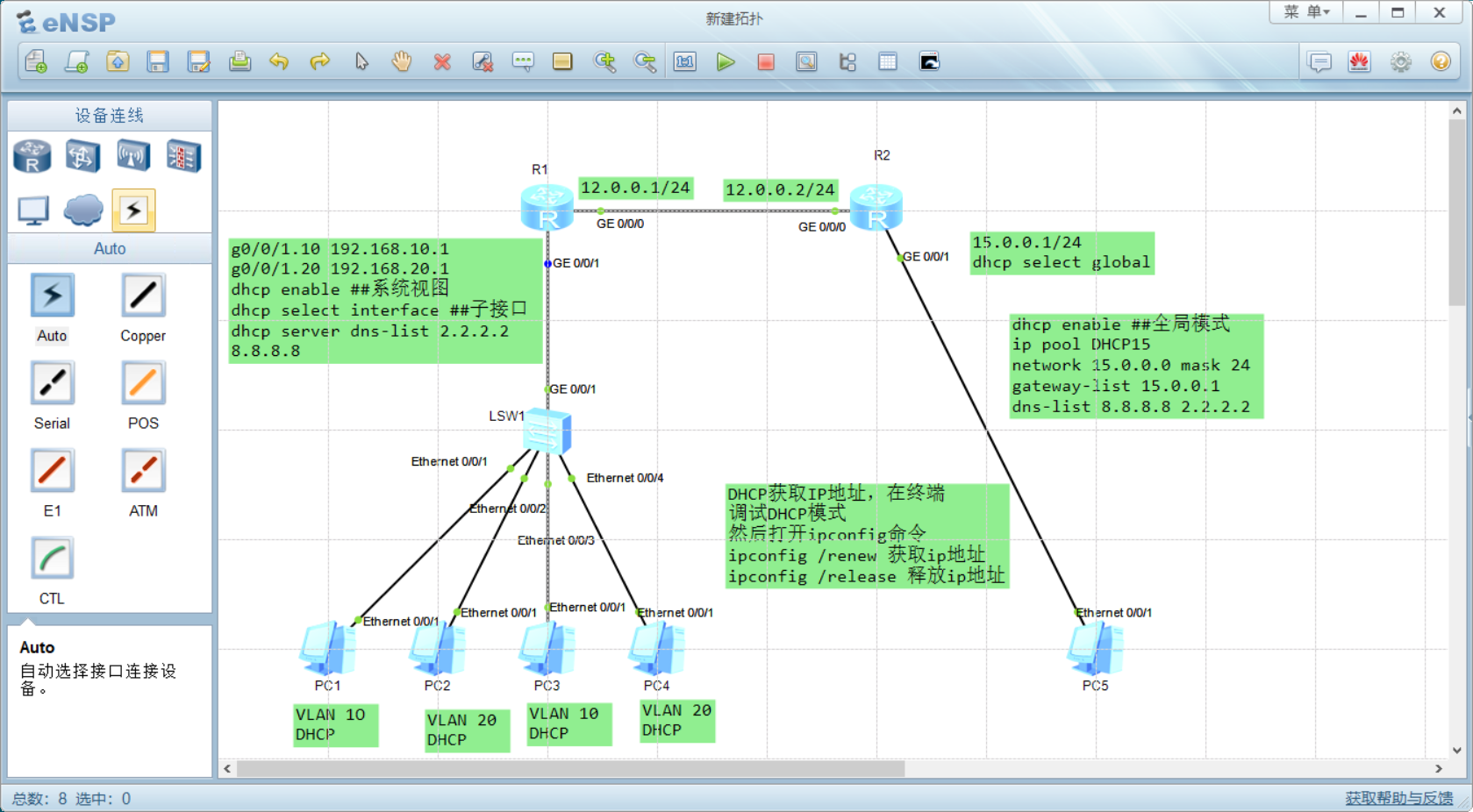
2.2 configure SW1 switch
[SW1]vlan batch 10 20
[SW1]int e0/0/1
[SW1-Ethernet0/0/1]p l a
[SW1-Ethernet0/0/1]p d v 10
[SW1-Ethernet0/0/1]un sh
[SW1-Ethernet0/0/1]int e0/0/2
[SW1-Ethernet0/0/2]p l a
[SW1-Ethernet0/0/2]p d v 20
[SW1-Ethernet0/0/2]un sh
[SW1-Ethernet0/0/2]int e0/0/3
[SW1-Ethernet0/0/3]p l a
[SW1-Ethernet0/0/3]p d v 10
[SW1-Ethernet0/0/3]un sh
[SW1-Ethernet0/0/4]int e0/0/4
[SW1-Ethernet0/0/4]p l a
[SW1-Ethernet0/0/4]p d v 20
[SW1-Ethernet0/0/4]un sh
[SW1-Ethernet0/0/4]int g0/0/1
[SW1-GigabitEthernet0/0/1]p l t
[SW1-GigabitEthernet0/0/1]p t a v a
[SW1-GigabitEthernet0/0/1]un sh
[SW1]dis int b
Ethernet0/0/1               up    up          0%     0%          0          0
Ethernet0/0/2               up    up          0%     0%          0          0
Ethernet0/0/3               up    up          0%     0%          0          0
Ethernet0/0/4               up    up          0%     0%
[SW1]dis cu
interface Ethernet0/0/1
 port link-type access
 port default vlan 10
interface Ethernet0/0/2
 port link-type access
 port default vlan 20
interface Ethernet0/0/3
 port link-type access
 port default vlan 10
interface Ethernet0/0/4
 port link-type access
 port default vlan 20
interface GigabitEthernet0/0/1
 port link-type trunk
 port trunk allow-pass vlan 2 to 4094
2.3 configure R1 router
Configure single arm routing first
interface GigabitEthernet0/0/0
 ip address 12.0.0.1 255.255.255.0
[R1]int g0/0/1.10
[R1-GigabitEthernet0/0/1.10]ip add 192.168.10.1 24
[R1-GigabitEthernet0/0/1.10]d t v 10
[R1-GigabitEthernet0/0/1.10]a b e
[R1-GigabitEthernet0/0/1.10]un sh
[R1]int g0/0/1.20
[R1-GigabitEthernet0/0/1.20]ip add 192.168.20.1 24
[R1-GigabitEthernet0/0/1.20]dot1q termination vid 20
[R1-GigabitEthernet0/0/1.20]arp broadcast enable
[R1-GigabitEthernet0/0/1.20]un sh
Reconfigure DNS
[R1]int g0/0/1.10
[R1-GigabitEthernet0/0/1.10]dhcp select interface
[R1-GigabitEthernet0/0/1.10]dhcp server dns-list 2.2.2.2 8.8.8.8
[R1-GigabitEthernet0/0/1.10]int g0/0/1.20
[R1-GigabitEthernet0/0/1.20]dhcp select interface
[R1-GigabitEthernet0/0/1.20]dhcp server dns-list 2.2.2.2 8.8.8.8
[R1-GigabitEthernet0/0/1.20]dis this
interface GigabitEthernet0/0/1.20
 dot1q termination vid 20
 ip address 192.168.20.1 255.255.255.0
 arp broadcast enable
 dhcp select interface
 dhcp server dns-list 2.2.2.2 8.8.8.8
[R1-GigabitEthernet0/0/1.20]int g0/0/1.10
[R1-GigabitEthernet0/0/1.10]dis this
interface GigabitEthernet0/0/1.10
 dot1q termination vid 10
 ip address 192.168.10.1 255.255.255.0
 arp broadcast enable
 dhcp select interface
 dhcp server dns-list 2.2.2.2 8.8.8.8
Configure routing
[R1]ip route-static 0.0.0.0 0.0.0.0 12.0.0.2
2.4 configure R2 router
Configure interface first
[R2]int g0/0/0
[R2-GigabitEthernet0/0/0]ip add 12.0.0.2 24
[R2-GigabitEthernet0/0/0]un sh
[R2-GigabitEthernet0/0/0]int g0/0/1
[R2-GigabitEthernet0/0/1]ip add 15.0.0.1 24
[R2-GigabitEthernet0/0/1]un sh
Reconfigure DHCP
[R2]dhcp enable
[R2-GigabitEthernet0/0/1]dhcp select global
[R2-GigabitEthernet0/0/1]q
[R2]ip pool DHCP15
[R2-ip-pool-DHCP15]network 15.0.0.0 mask 24
[R2-ip-pool-DHCP15]gateway-list 15.0.0.1
[R2-ip-pool-DHCP15]dns-list 8.8.8.8 2.2.2.2
[R2-ip-pool-DHCP15]dis this
ip pool DHCP15
 gateway-list 15.0.0.1
 network 15.0.0.0 mask 255.255.255.0
 dns-list 8.8.8.8 2.2.2.2
[R2]ip route-static 192.168.10.0 24 12.0.0.1
[R2]ip route-static 192.168.20.0 24 12.0.0.1
2.5 PC end test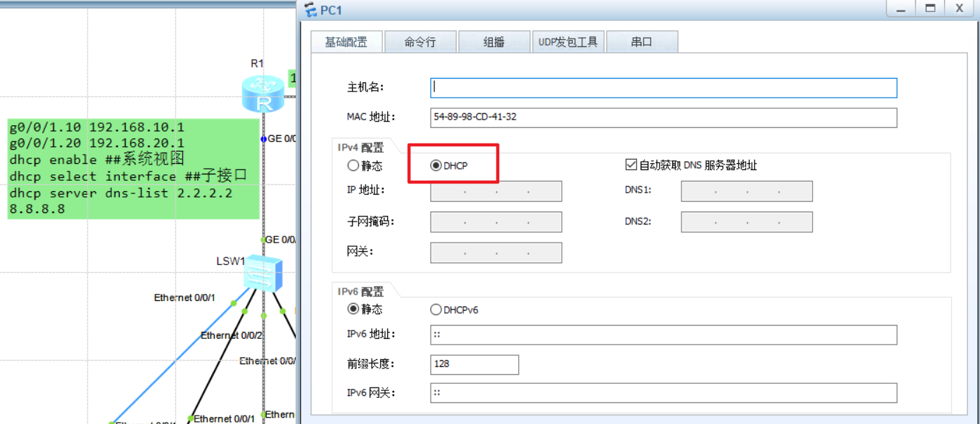
Set up DHCP to reapply to other PC s and view other addresses
Ipconfig /renew to retrieve ip address
IP address released by Ipconfig /release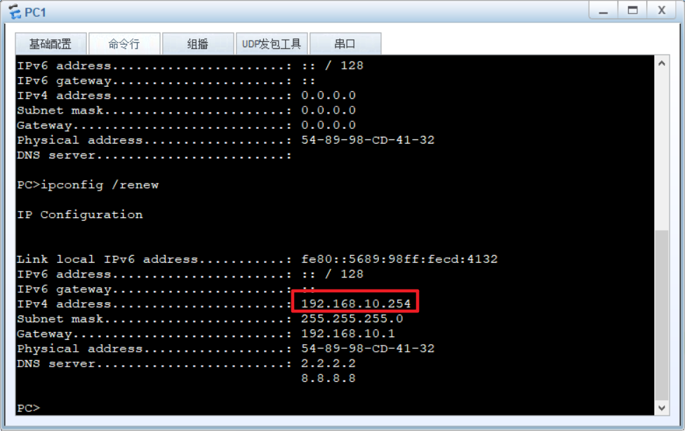
Use other PCs to ping 192.168.10.254, all of which can be pinged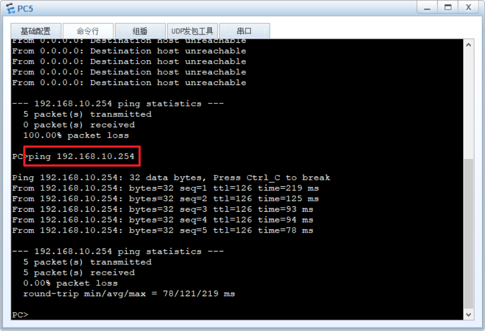
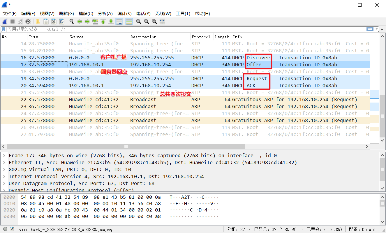
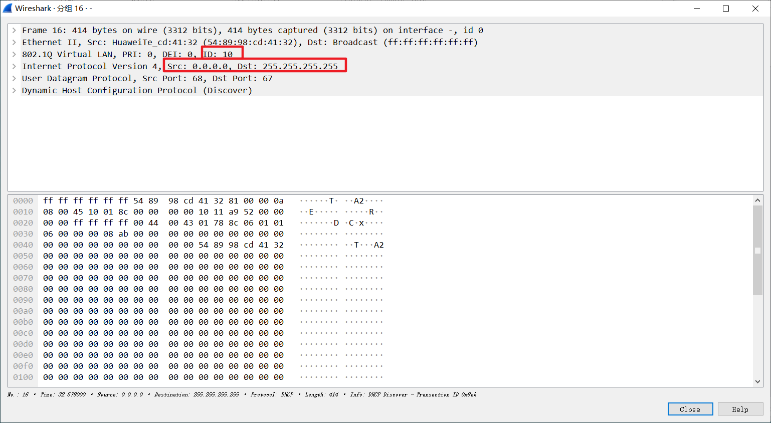
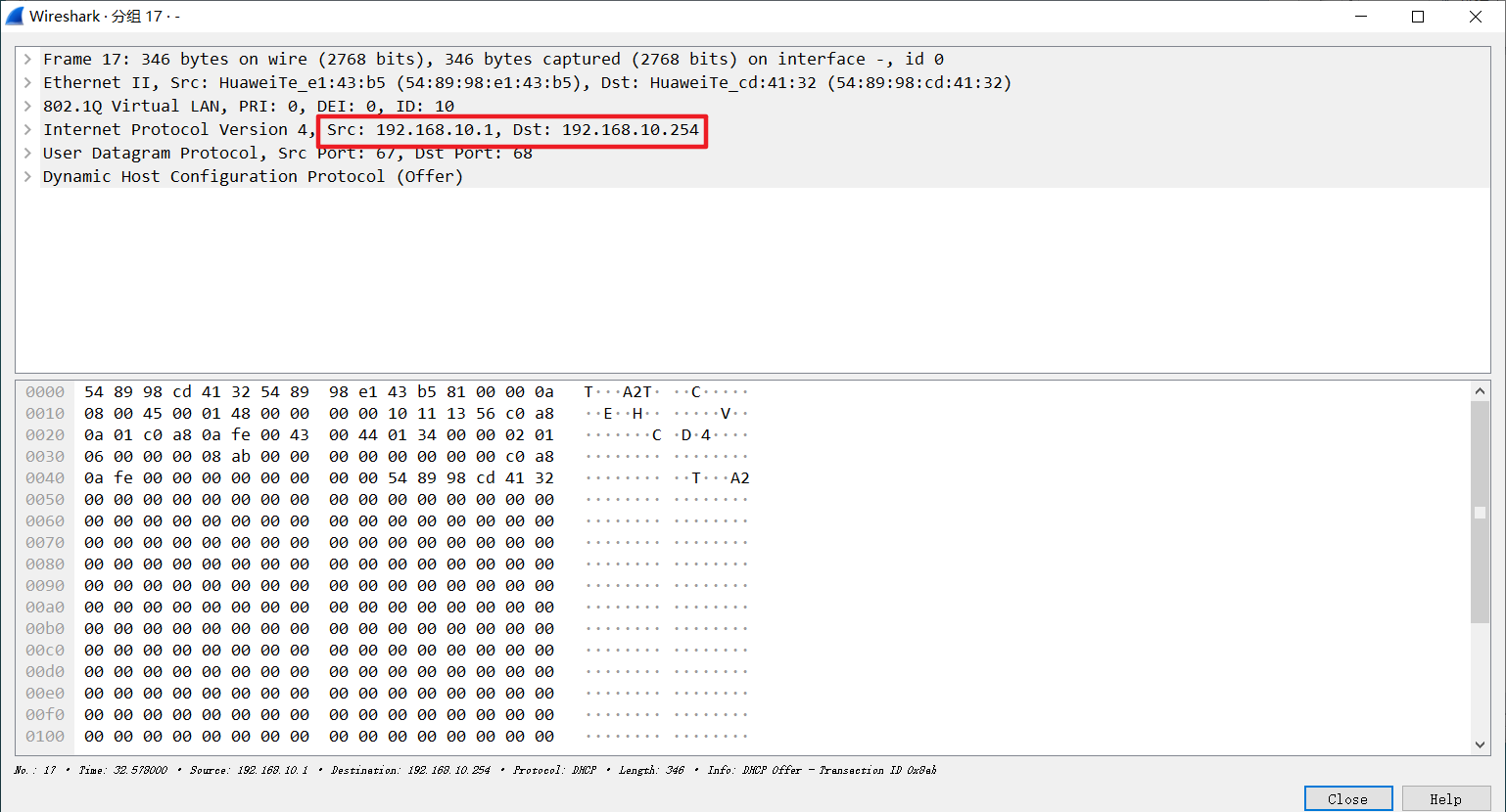
2.4 packet capturing study DHCP message