**ESP8266 Module Test**
ESP8266-01s Packaging Diagram: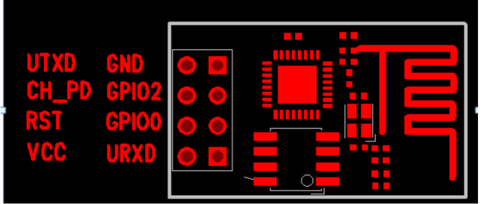
ESP8266 and Single Chip Connection:
ESP: Single-chip computer
UTXD RXD
GND GND
CH_PD(EN) (works for high level modules).
GPIO2 must be connected to a high level (internal has been raised, do not care)
RST (low level reset, high level operation)
GPIO0 is normally left unattended and low level when burning firmware
VCC 3.3V
URXD TXD
Description: After getting the module, test the module, only need to connect 5 wires, VCC, GND, UTXD, URXD, CH_PD (EN)
Once connected, AT command test can be carried out.
Note: (PC test module) If it is directly connected to USB to TTL, then RX and TX are crossed, if it is connected to single-chip computer, TX is connected to TX, RX is connected to RX, (single-chip computer test) After downloading the program, TX and RX are crossed and can communicate normally.
PC test:
When the module and computer are connected, AT commands can be executed in the following order (1-6):
AT Directive:
1.AT+CWMODE=X
Function: Set working mode instructions:
------ Station mode (let module connect to router or hotspot, module as client)
------ AP mode (module itself is a hot spot, mobile phone and computer can connect, module as server)
-------Station+AP mode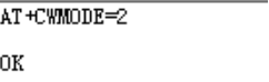
Example: AT+CWMODE=2
2.AT+RST
Function: Restart directive (a restart is required after setting a new working mode to take effect)
Example: AT+RST
3.AT+ CWSAP= ,,,
Function: Configure AP parameters (directives only work when AP mode is turned on)
ssid:Access point name
pwd: Password string type, up to 64 bytes long.
chl: channel number 0,1,2,3,4
ecn: encryption method: (0-OPEN, 1-WEP, 2-WPA_PSK, 3-WPA2_PSK, 4-WPA_WPA2_PSK)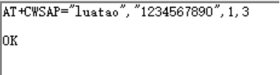
Example: AT+CWSAP="luatao", "1234567890", 1,3
4.AT+CIFSR
Function: View the IP address of this module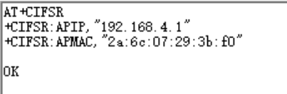
Example: AT+CIFSR
5.AT+CIPMUX=1
Function: Set up multi-connection mode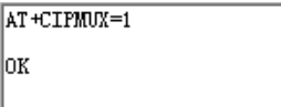
Example: AT+CIPMUX=1
6.AT+CIPSERVER=,
Function: Create Server
mode:
0--- Turn off SERVER mode
1--- Turn on SERVER mode
Port: Port number (default 333)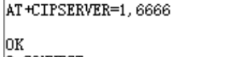
Example: AT+CIPSERVER=1,6666
Note: AT+CIPMUX=1 can only start the server, shutting down SERVER mode requires restarting AT+RST
Listening is automatically established after SERVER is turned on, and a connection is automatically established in sequence when there is Client access.
7.AT+CIPMUX?
Function: See if this module establishes multiple connections
0------- One way connection
1------ Multiplex connection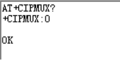
Example: AT+CIPMUX?
After the above program is executed, the module setup is completed, and the communication can be tested by sending messages from the mobile client.
Step 1: Turn on your mobile phone and connect the WIFI module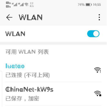
Step 2: Open Network Debugging APP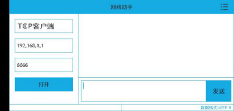
Once configured on the diagram, click Open if the connection is successful
Print 0,CONNECT on PC serial port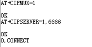
Single-chip test:
Step 1: Download the program.
In order for the single-chip computer to send data to the mobile phone, you need to send a command
Two-way data transmission
Multi-connection mode:
AT+CIPSEND=0,10
Single connection mode:
AT+CIPSEND=10
Code sent:
Send_String("AT+CIPSEND=0,10\r\n"); //Send 10 data
Delay1000ms();
Send_String("hello world"); //Send data to mobile phone
Delay1000ms();
The rest is to connect to the module, open network debugging, and send data tests.
Code:
ESP8266.h
#ifndef ESP8266
#define ESP8266
sbit LED=P6^0;
extern uchar Receive;//Received value
extern void Delay1000ms()        ;        //@24.000MHz
extern void Uart1_Init(void);        //9600bps@24.000MHz
extern void ESP8266_Init();//ESP8266 Serial Port Sends Two Instructions
extern void Send_String(uchar *p);//Send String
#endif
ESP8266.c
#include<All.h>
uchar Receive;//Received value
/*********************************
 * @Function name: Delay1000ms
 * @Description: Delay 1s
 * @Parameter: None
 * @Return value: None
 *********************************/
void Delay1000ms()                //@24.000MHz
{
        unsigned char i, j, k;
        _nop_();
        _nop_();
        i = 92;
        j = 50;
        k = 238;
        do
        {
                do
                {
                        while (--k);
                } while (--j);
        } while (--i);
}
/*********************************
 * @Function name: Uart1_Init
 * @Description: Serial port 1 initialization function timer 1 generates baud rate, configures the value of the register
 * @Parameter: None
 * @Return value: None
 *********************************/
void Uart1_Init(void)                //9600bps@24.000MHz
{
        SCON = 0x50;                //8-bit data, variable baud rate
        AUXR |= 0x04;                //Timer 2, clock 1T
        T2L = 0x8F;                //Set Timer Initial Value
        T2H = 0xFD;                //Set Timer Initial Value
        //IE2|=0x40; //Turn on timer 2 interrupt
        IE2&=0xfb;//Suppress Timer 2 Interrupt
        AUXR |= 0x10;                //Start Timer 2
//        PS=0; //Serial Port 1 Interrupt Priority Control Bit PS=0; Priority 0
//                                                        //PS=1; priority 1
        EA=1;    //Turn on interrupt master switch
        ES=0;       //Serial port interrupt allowable bits
}
/*********************************
 * @Function name: Send_Value
 * @Description: Send a character through the serial port
 * @Parameter: Character sent by value
 * @Return value: None
 *********************************/
void Send_Value(uchar value)
{
       ES=0; //Close Serial Port 1 Interrupt
       SBUF=value; //Send a character
       while(!TI); //Waiting for send to complete
       TI=0; //Send Complete Interrupt Bit Zeroing
       ES=1; //Open Serial Port 1 Interrupt
}
/*********************************
 * @Function name: Send_String
 * @Description: Send a string through the serial port
 * @Parameter: *p The first address of the string sent
 * @Return value: None
 *********************************/
void Send_String(uchar *p)
{
   while(*p)
   {
     Send_Value(*p);//Send a Data
           p++;//Move Address Backward
   }
}
/*********************************
 * @Function name: ESP8266_Init
 * @Description: ESP8266 sends two instructions to initialize
 * @Parameter: None
 * @Return value: None
 *********************************/
void ESP8266_Init()
{
   uchar a[]="AT+CIPMUX=1\r\n";     //Set up multiple connection mode
   uchar b[]="AT+CIPSERVER=1,6666\r\n";//Create Server

    Send_String(a);//Send the first AT command
    Delay1000ms();//Waiting for module response
        Send_String(b);//Send second AT command
    Delay1000ms();
}
/*********************************
 * @Function name: Uart1
 * @Description: Interrupt the program, after +IPD,x,x: useful data is stored in the receive array
 * @Parameter: None
 * @Return value: None
 *********************************/
void Uart1() interrupt 4
{
        static uchar Flag=0;//Status flag bits
       if(RI)  //Enter receive interrupt flag bit
       {
                RI=0;  //Receive interrupt flag bit zeroing
                if(Flag==1)  //What's received here is the actual value sent
                {
                        Receive=SBUF;//Store received characters
                        Flag=0;
                }
                if(SBUF==':')      //This must be below
                                   Flag=1;
       }
}
All.h
#include<STC8.h>
#include<intrins.h>

typedef unsigned char uchar;
typedef unsigned int uint;

#include<ESP8266.h>  //ESP8266wifi module
//Insert a code snippet here
main.c
#include<All.h>
void main()
{
 Uart1_Init();
 ESP8266_Init();
   while(1)
   {
  if(Receive=='A')
   LED=0;    //Light on
  else if (Receive=='B')
   LED=1;    //Light goes out
  else if(Receive=='a')
  {
  Send_String("AT+CIPSEND=0,10\r\n");//Send 10 data
  Delay1000ms();
  Send_String("hello world");
  Delay1000ms();
  }

