What is cluster
- A group of computers interconnected by a high-speed network and managed in a single system mode.
- Many servers are put together to provide the same service, which looks like only one server in the client.
- It can obtain relatively high benefits in performance, reliability and flexibility at a lower cost.
- Task scheduling is the core technology of cluster system.
Cluster classification
-
High performance computing cluster HPC
- solve complex scientific problems through parallel applications developed in clusters -
Load balancing (LB) cluster
- the client load is shared equally in the computer cluster as much as possible -
High availability (HA) cluster
- avoid single point of failure, when a system fails, it can be quickly migrated
Load balancing type
-DNS load balancing
DNS load balancing is the most basic and simple way. A domain name is resolved to multiple IPS through DNS, and each IP corresponds to different server instances, so the traffic scheduling is completed. Although the conventional load balancer is not used, the simple load balancing function is also completed.
-Hardware load balancing
hardware load balancing is to realize load balancing function through special hardware equipment, similar to switch and router, which is a special network equipment for load balancing. At present, there are two typical hardware load balancing devices in the industry: F5 and A10. This kind of equipment has strong performance and powerful function, but its price is very expensive. Generally, only "tuhao" companies can use this kind of equipment, which can not be afforded by ordinary business level companies. Secondly, the business volume is not so large, and using these equipment is also a waste.
-Software load balancing
software load balancing can run load balancing software on ordinary servers to realize load balancing function. At present, Nginx, HAproxy and LVS are common.
difference:
.
. The default load balancing software used by OpenStack is HAproxy
.
Introduction to load balancing LVS
the architecture and principle of LB cluster is very simple, that is, when the user's request comes, it will be directly distributed to the Director Server, and then it will distribute the user's request to the back-end real server intelligently and evenly according to the set scheduling algorithm. In order to avoid different data requested by users on different machines, shared storage is needed to ensure that the data requested by all users is the same.
LVS is the abbreviation of Linux Virtual Server, that is, Linux Virtual Server. This is an open source project initiated by Dr. Zhang wensong. Now LVS is a part of Linux kernel standard. The technical goal of LVS is to achieve a high performance and high availability Linux Server cluster through LVS load balancing technology and Linux operating system, which has good reliability, scalability and operability. In order to achieve the best performance at a low cost. LVS is an open source software project to realize load balancing cluster. LVS architecture can be logically divided into scheduling layer, Server cluster layer and shared storage layer.
Basic working principle of LVS
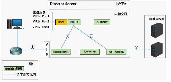
1. When the user initiates a request to the load balancing scheduler (Director Server), the scheduler sends the request to the kernel space
2. The pre routing chain will first receive the user's request, judge whether the target IP is the local IP, and send the data packet to the INPUT chain
3.IPVS works on the INPUT chain. When the user request arrives at INPUT, IPVS will compare the user request with the defined cluster service. If the user request is the defined cluster service, then IPVS will forcibly modify the target IP address and port in the packet and send the new packet to the post routing chain
4. After receiving the packet, the posting link finds that the destination IP address just happens to be its own back-end server. At this time, the packet is finally sent to the back-end server by routing
LVS load balancing scheduling algorithm
- LVS currently implements 10 scheduling algorithms
- There are four common scheduling algorithms
- polling
- distribute client requests to Real Server evenly
- weighted polling
Polling scheduling based on Real Server weight
- minimum connection
- select the server with the least connections
- weighted least connection
- select the server with the least connections according to the Real Server weight value
- source address hash
LVS cluster composition
- front end: load balancing layer
- composed of one or more load schedulers
- middle: server group layer
- consists of a set of servers that actually run application services
- bottom: data sharing storage tier
- storage area that provides shared storage space
Related terms
DS: Director Server. Refers to the front-end load balancer node.
RS: Real Server. Back end real working server.
CIP: Client IP, indicating the Client IP address.
VIP: Virtual IP, which indicates the IP address that load balancing provides for external access. Generally, load balancing IP will be highly available through Virtual IP.
RIP: RealServer IP, which represents the real server IP address of the load balancing backend.
DIP: Director IP, which indicates the IP address of the communication between the load balancing and the back-end server.
LVS working mode
LVS/NAT: network address translation
- virtual server through network address translation
- scheduler performance becomes a bottleneck in large concurrent access
-LVS/DR: direct routing
- direct use of routing technology to achieve virtual server
- the node server needs to be configured with VIP, pay attention to MAC address broadcast
-LVS/TUN: IP tunnel
- tunnel virtual server
Principle of each working mode of LVS
For more details, please refer to the blog: https://blog.csdn.net/liwei0526vip/article/details/103104483
1. Network address translation (LVS-NAT)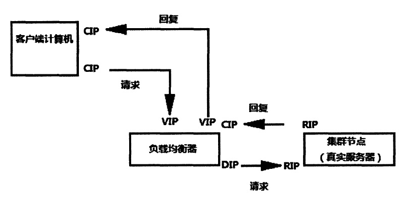
1. When the user requests to arrive at the Director Server, the requested data message will first arrive at the preouting chain in the kernel space. At this time, the source IP of the message is CIP and the target IP is VIP.

2.PREROUTING checks that the destination IP of the packet is local and sends the packet to the INPUT chain

3.IPVS compares whether the service requested by the packet is a cluster service. If so, modify the destination IP address of the packet to the back-end server IP, and then send the packet to the posting chain. At this time, the source IP of the message is CIP, and the target IP is rip 4. The posting chain sends the packet to the Real Server through routing

5.Real Server finds that the target is its own IP, and starts to build response message to send back to Director Server. At this time, the source IP of the message is RIP, and the target IP is CIP

6. Before responding to the client, the director server will change the source IP address to its own VIP address, and then respond to the client. At this time, the source IP of the message is VIP and the target IP is CIP
2. Direct routing (LVS-DR)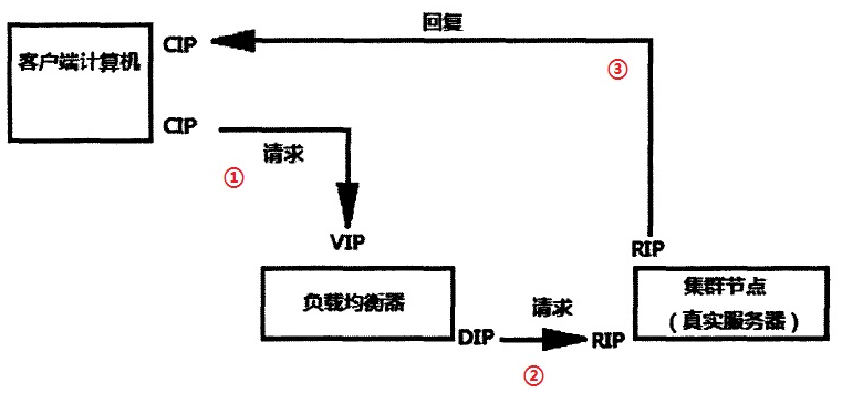
1. When the user requests to arrive at the Director Server, the requested data message will first arrive at the preouting chain in the kernel space. At this time, the source IP of the message is CIP and the target IP is VIP.

2.PREROUTING checks that the destination IP of the packet is local and sends the packet to the INPUT chain

3.IPVS compares whether the service requested by the packet is a cluster service. If so, change the source MAC address [CIP] in the request message to the MAC address of DIP, change the destination MAC address [VIP] to the MAC address of RIP, and then send the packet to the post routing chain [LVS]. At this time, neither the source IP nor the destination IP has been modified. Only the MAC address with the source MAC address of DIP and the destination MAC address of RIP have been modified

4. Since DS and RS are in the same network, they are transmitted through two layers. The post routing chain checks the MAC address [ARP broadcast] whose target MAC address is RIP, and then the packet will be sent to the Real Server.

5.RS finds that the MAC address of the request message is its own MAC address, so it receives the message. After processing, the response message is transmitted to eth0 network card through its own lo interface, and then [ARP broadcast] is sent out. At this time, the source IP address is VIP and the target IP is CIP

be careful:
 If there is no external IP set for RS, RS will broadcast ARP to find CIP. If there is no internal network, it will be submitted to the gateway. The gateway will directly send out the external network, which may increase the pressure on the gateway

6. The response message is finally delivered to the client
Features: a Mac address is added to let the real server find the client and send the response message directly. The IP address of the client (CIP) and the load balancer in the whole process have not changed, but the Mac address has changed. The purpose is to let the client know that you send the requested message and respond to your message by one person.
3.IP tunnel (LVS-TUN)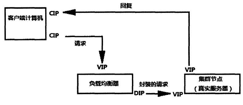
1. When the user requests to arrive at the Director Server, the requested data message will first arrive at the preouting chain in the kernel space. At this time, the source IP of the message is CIP and the target IP is VIP.

2.PREROUTING checks that the destination IP of the packet is local and sends the packet to the INPUT chain

3.IPVS compares whether the service requested by the packet is a cluster service. If so, a layer of IP message is encapsulated at the first part of the request message. The source IP is DIP and the target IP is RIP. Then send it to the posting chain. At this time, the source IP is DIP, the target IP is RIP ④, and the posting chain sends the data packet to RS according to the latest encapsulated IP message (because there is an additional IP header in the outer layer, it can be understood that it is transmitted through the tunnel at this time). At this time, the source IP is DIP and the target IP is RIP

4. When RS receives the message and finds that it is its own IP address, it will receive the message. After removing the outermost IP, it will be found that there is a layer of IP head inside, and the target is its own lo interface VIP. Then RS starts to process the request. After processing, RS will send it to eth0 network card through lo interface, and then transmit it to the outside. At this time, the source IP address is VIP and the destination IP is CIP

5. The response message is finally delivered to the client
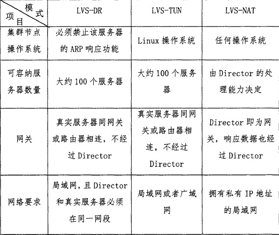
Comparison of three working modes
ipvsadm command options
  ipvsadm -A create virtual server
  ipvsadm -E modify virtual server
  ipvsadm -D delete virtual server

  ipvsadm -t set cluster address (VIP,Virtual IP)
  ipvsadm -s specifies the clustering algorithm ----- > RR (polling), WRR (weighted polling), LC (least connection), WLC (weighted least connection), sh(ip_hash)

  ipvsadm -a add real server
  ipvsadm -e modify real server
  ipvsadm -d delete real server

  ipvsadm -r specifies the address of the real server
  ipvsadm -w sets the weight for the node server, which is 1 by default

  ipvsadm -C clear all
  ipvsadm -L view LVS rule table -- > generally used with n, output in digital form (- Ln)

  ipvsadm -m uses NAT mode
  Ipvsadm-g uses DR mode
  ipvsadm -i using TUN mode
LVS-NAT mode Practice
NAT mode features
RS should use private address, RS gateway must point to DIP (dispatcher IP)
DIP and RIP must be in the same network segment,
Both request and response messages need to go through Director Server. In high load scenarios, Director Server is easy to become a performance bottleneck
 Supports port mapping
 RS can use any operating system
 Defect: the pressure on the director server will be great, and the request and response need to go through the director server
Environment introduction
client: 192.168.4.132 (4 network segments act as external network)
load balancing server: ens37: 192.168.4.133 (4 network segments act as external network) ens33: 192.168.2.130 (test3)
backend server 1: 192.168.2.128 (localhost) gateway: 192.168.2.130
backend server 2: 192.168.2.129 (test2) gateway: 192.168.2.130
kernel version: 3.10.0-862.el7.x86_ Sixty-four
system version: CentOS 7.5
be careful:
1. Two back-end servers must be configured with gateway address, and the gateway address must be specified as the internal network address of the scheduling server. (i.e. 192.168.2.130)
2.LVS requires LVS server (scheduler) and Real server to be in the same network segment no matter in NAT or DR mode. NAT needs to take LVS server (scheduler) as the default gateway of each Real server,
1, Basic environment configuration
1. Install Nginx on 128 / 129 of two back-end servers respectively
[root@localhost ~]# wget http://nginx.org/download/nginx-1.16.1.tar.gz

[root@localhost ~]# yum -y install gcc pcre-devel openssl-devel

[root@localhost ~]# useradd -s /sbin/nologin nginx / / create a user who is not allowed to log on to the interpreter (for security)

[root@localhost ~]# id nginx
uid=1001(nginx) gid=1001(nginx) group=1001(nginx)

[root@localhost ~]# tar -xf nginx-1.16.1.tar.gz

[root@localhost ~]# cd nginx-1.16.1

[root@localhost nginx-1.16.1]# ./configure --prefix=/usr/local/nginx --user=nginx --group=nginx --with-http_ssl_module

         --prefix=/usr/local/nginx                   //Specify installation path
         --user=nginx                               //Specify users
         --group=nginx                              //Specify group
         --with-http_ssl_module                    //install ssl Module, open the SSL Encryption function(Install as many modules as you need)
  ......
  ......
  nginx modules path: "/usr/local/nginx/modules"
  nginx configuration prefix: "/usr/local/nginx/conf"
  nginx configuration file: "/usr/local/nginx/conf/nginx.conf"
  nginx pid file: "/usr/local/nginx/logs/nginx.pid"
  nginx error log file: "/usr/local/nginx/logs/error.log"
  nginx http access log file: "/usr/local/nginx/logs/access.log"
  nginx http client request body temporary files: "client_body_temp"
  nginx http proxy temporary files: "proxy_temp"
  nginx http fastcgi temporary files: "fastcgi_temp"
  nginx http uwsgi temporary files: "uwsgi_temp"
  nginx http scgi temporary files: "scgi_temp"

[root@localhost nginx-1.16.1]#  Make & & make install / / compile and install
......
	'/usr/local/nginx/conf/scgi_params.default'
test -f '/usr/local/nginx/conf/nginx.conf' \
	|| cp conf/nginx.conf '/usr/local/nginx/conf/nginx.conf'
cp conf/nginx.conf '/usr/local/nginx/conf/nginx.conf.default'
test -d '/usr/local/nginx/logs' \
	|| mkdir -p '/usr/local/nginx/logs'
test -d '/usr/local/nginx/logs' \
	|| mkdir -p '/usr/local/nginx/logs'
test -d '/usr/local/nginx/html' \
	|| cp -R html '/usr/local/nginx'
test -d '/usr/local/nginx/logs' \
	|| mkdir -p '/usr/local/nginx/logs'
make[1]: Leave directory“/root/nginx-1.16.1"

[root@localhost ~]# /usr/local/nginx/sbin/nginx -V
nginx version: nginx/1.16.1
built by gcc 4.8.5 20150623 (Red Hat 4.8.5-39) (GCC)
built with OpenSSL 1.0.2k-fips  26 Jan 2017
TLS SNI support enabled
configure arguments: --prefix=/usr/local/nginx --user=nginx --group=nginx --with-http_ssl_module

[root@test2 ~]# /usr/local/nginx/sbin/nginx -V
nginx version: nginx/1.16.1
built by gcc 4.8.5 20150623 (Red Hat 4.8.5-39) (GCC)
built with OpenSSL 1.0.2k-fips  26 Jan 2017
TLS SNI support enabled
configure arguments: --prefix=/usr/local/nginx --user=nginx --group=nginx --with-http_ssl_module
2. Create test page
[root@localhost ~]# echo "I am 192.168.2.128" > /usr/local/nginx/html/index.html

[root@test2 ~]# echo "I am 192.168.2.129" > /usr/local/nginx/html/index.html
3. Start Nginx
[root@localhost nginx-1.16.1]# /usr/local/nginx/sbin/nginx

[root@localhost nginx-1.16.1]# netstat -antulp | grep :80
tcp        0      0 0.0.0.0:80              0.0.0.0:*               LISTEN      6079/nginx: master

//perhaps[root@localhost nginx-1.16.1]# netstat -antulp | grep nginx
tcp        0      0 0.0.0.0:80              0.0.0.0:*               LISTEN      6079/nginx: master
3. Turn off firewall and selinux
Both back-end servers need to operate.
[root@test2 ~]# systmctl stop firewalld

[root@test2 ~]# setenforce 0

[root@test2 ~]# getenforce
Disabled

[root@test2 ~]# vim /etc/sysconfig/selinux / / permanently shut down selinux
SELINUX=disabled
2, Deploy LVS-NAT mode scheduler
1. Confirm whether the route forwarding function of the dispatcher is on (it must be on)
[root@test3 ~]# cat /proc/sys/net/ipv4/ip_forward
1

//If not, then:
[root@test3 ~]# echo 1 > /proc/sys/net/ipv4/ip_forward

[root@test3 ~]# echo "net.ipv4.ip_forward = 1" >> /etc/sysctl.conf
     ////Modify the configuration file and set the routing and forwarding permanent rules
2. The dispatcher adds another network card
[root@test3 ~]# ifconfig
ens33: flags=4163<UP,BROADCAST,RUNNING,MULTICAST>  mtu 1500
        inet 192.168.2.130  netmask 255.255.255.0  broadcast 192.168.2.255
        inet6 fe80::1e8a:7d4a:beb0:fd6c  prefixlen 64  scopeid 0x20<link>
        inet6 fe80::2c27:a02c:731a:2219  prefixlen 64  scopeid 0x20<link>
        ether 00:0c:29:53:71:a2  txqueuelen 1000  (Ethernet)
        RX packets 66342  bytes 15217275 (14.5 MiB)
        RX errors 0  dropped 0  overruns 0  frame 0
        TX packets 13974  bytes 1254299 (1.1 MiB)
        TX errors 0  dropped 0 overruns 0  carrier 0  collisions 0

lo: flags=73<UP,LOOPBACK,RUNNING>  mtu 65536
        inet 127.0.0.1  netmask 255.0.0.0
        inet6 ::1  prefixlen 128  scopeid 0x10<host>
        loop  txqueuelen 1000  (Local Loopback)
        RX packets 48  bytes 3781 (3.6 KiB)
        RX errors 0  dropped 0  overruns 0  frame 0
        TX packets 48  bytes 3781 (3.6 KiB)
        TX errors 0  dropped 0 overruns 0  carrier 0  collisions
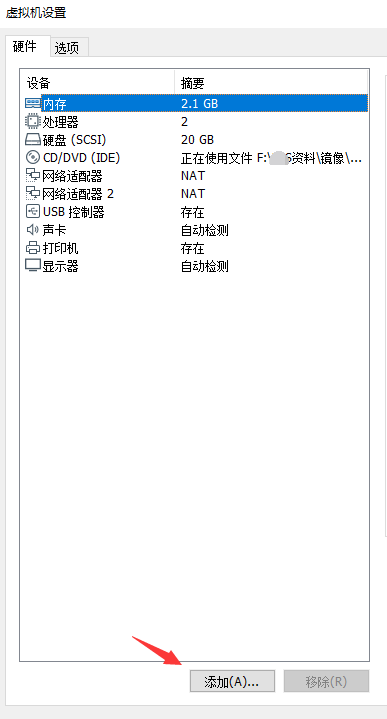
[root@test3 ~]# ifconfig
ens33: flags=4163<UP,BROADCAST,RUNNING,MULTICAST>  mtu 1500
        inet 192.168.2.130  netmask 255.255.255.0  broadcast 192.168.2.255
        inet6 fe80::1e8a:7d4a:beb0:fd6c  prefixlen 64  scopeid 0x20<link>
        inet6 fe80::2c27:a02c:731a:2219  prefixlen 64  scopeid 0x20<link>
        ether 00:0c:29:53:71:a2  txqueuelen 1000  (Ethernet)
        RX packets 66416  bytes 15223172 (14.5 MiB)
        RX errors 0  dropped 0  overruns 0  frame 0
        TX packets 13996  bytes 1256226 (1.1 MiB)
        TX errors 0  dropped 0 overruns 0  carrier 0  collisions 0

ens37: flags=4163<UP,BROADCAST,RUNNING,MULTICAST>  mtu 1500
        inet 192.168.4.133  netmask 255.255.255.0  broadcast 192.168.4.255
        inet6 fe80::7e5e:fea8:ba8e:ee18  prefixlen 64  scopeid 0x20<link>
        ether 00:0c:29:53:71:ac  txqueuelen 1000  (Ethernet)
        RX packets 5018  bytes 385651 (376.6 KiB)
        RX errors 0  dropped 0  overruns 0  frame 0
        TX packets 2524  bytes 269779 (263.4 KiB)
        TX errors 0  dropped 0 overruns 0  carrier 0  collisions 0

lo: flags=73<UP,LOOPBACK,RUNNING>  mtu 65536
        inet 127.0.0.1  netmask 255.0.0.0
        inet6 ::1  prefixlen 128  scopeid 0x10<host>
        loop  txqueuelen 1000  (Local Loopback)
        RX packets 48  bytes 3781 (3.6 KiB)
        RX errors 0  dropped 0  overruns 0  frame 0
        TX packets 48  bytes 3781 (3.6 KiB)
        TX errors 0  dropped 0 overruns 0  carrier 0  collisions 0
3. Two back-end servers configure the gateway address
[root@localhost ~]# cat /etc/sysconfig/network-scripts/ifcfg-ens37
TYPE=Ethernet
PROXY_METHOD=none
BROWSER_ONLY=no
BOOTPROTO="static"
DEFROUTE=yes
IPV4_FAILURE_FATAL=no
IPV6INIT=yes
IPV6_AUTOCONF=yes
IPV6_DEFROUTE=yes
IPV6_FAILURE_FATAL=no
IPV6_ADDR_GEN_MODE=stable-privacy
NAME=ens37
UUID=2d899e46-1b9d-40d5-9fed-8a88cb181d79
DEVICE=ens37
ONBOOT=yes
IPADDR="192.168.2.128"
PREFIX="24"
GATEWAY="192.168.2.130"     //The gateway address is configured as the internal network address of the scheduler
DNS1="8.8.8.8"

[root@test2 ~]#  cat /etc/sysconfig/network-scripts/ifcfg-ens33
TYPE=Ethernet
PROXY_METHOD=none
BROWSER_ONLY=no
BOOTPROTO="static"
DEFROUTE=yes
IPV4_FAILURE_FATAL=no
IPV6INIT=yes
IPV6_AUTOCONF=yes
IPV6_DEFROUTE=yes
IPV6_FAILURE_FATAL=no
IPV6_ADDR_GEN_MODE=stable-privacy
NAME=ens33
UUID=2d899e46-1b9d-40d5-9fed-8a88cb181d65
DEVICE=ens33
ONBOOT=yes
IPADDR="192.168.2.129"
PREFIX="24"
GATEWAY="192.168.2.130"    //The gateway address is configured as the internal network address of the scheduler
DNS1="8.8.8.8"

[root@localhost ~]# systemctl restart network

[root@test2 ~]# systemctl restart network
The following steps operate on the scheduler
||
4. Create a cluster scheduling server
[root@test3 ~]# yum -y install ipvsadm

[root@test3 ~]# ipvsadm -A -t 192.168.4.133:80 -s wrr / / / / / create a virtual cluster server and set the scheduling algorithm to weighted polling wrr
5. Add real server group
[root@test3 ~]# ipvsadm -a -t 192.168.4.133:80 -r 192.168.2.128 -w 1 -m

[root@test3 ~]# ipvsadm -a -t 192.168.4.133:80 -r 192.168.2.129 -w 2 -m
4. View the rule list and save the rule
[root@test3 ~]# ipvsadm -Ln
IP Virtual Server version 1.2.1 (size=4096)
Prot LocalAddress:Port Scheduler Flags
  -> RemoteAddress:Port           Forward Weight ActiveConn InActConn
TCP  192.168.4.133:80 wrr
  -> 192.168.2.128:80             Masq    1      0          0
  -> 192.168.2.129:80             Masq    2      0          0

[root@test3 ~]# ipvsadm-save -n > /etc/sysconfig/ipvsadm-config
3, Test on client
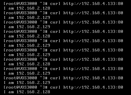
you can see that every time we execute a curl command (equivalent to refreshing a web page), the scheduler will poll different back-end real servers according to the weight value.
When we stop the two back-end servers in turn, will the scheduler take over?
1. Stop the nginx service of backend 129 server
[root@test2 ~]# /usr/local/nginx/sbin/nginx -s stop
2. Use client access to view polling results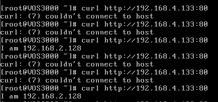
3. Stop the backend 128 server nginx server again
[root@localhost ~]# /usr/local/nginx/sbin/nginx -s stop
4. Use client access again to view the polling results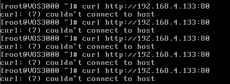
you can see that the load balancing scheduling server does not replace the work.