1, Introduction of firewall hot standby
Overview of dual hot standby
- Dual hot standby is to solve single point of failure and realize smooth transition of business (session table needs to be synchronized)
- The hot standby modes of Huawei firewall include: hot standby mode and load balancing mode
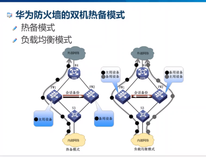
- The main standby backup refers to that under normal circumstances, only the main equipment processes the business and the standby equipment is idle; when the interface, link or the whole machine of the main equipment fails, the standby equipment switches to the main equipment and replaces the main equipment to process the business
- The so-called load sharing can also be called "mutual primary backup", that is, two devices handle business at the same time. When one device sends a fault, the other device will immediately undertake its business to ensure that the business that needs to be transmitted through this device will not be interrupted
VGMP introduction
- VGMP is a private agreement of Huawei. The VGMP group is defined in the VGMP protocol. FW realizes the management of the primary and standby state of the device based on the VGMP group
- VGMP protocol solves the inconsistency of backup group switching
Priority of VGMP
- Middle and low end: Active device priority is 65001, Standby device priority is 6500
- High end: initial priority of VGMP group = number of cards on 45000+1000*LPU board + number of CPU s on 2*SPU board
- USG6000, the initialization priority of NGFW Module is 45000
State transition and working process of VGMP
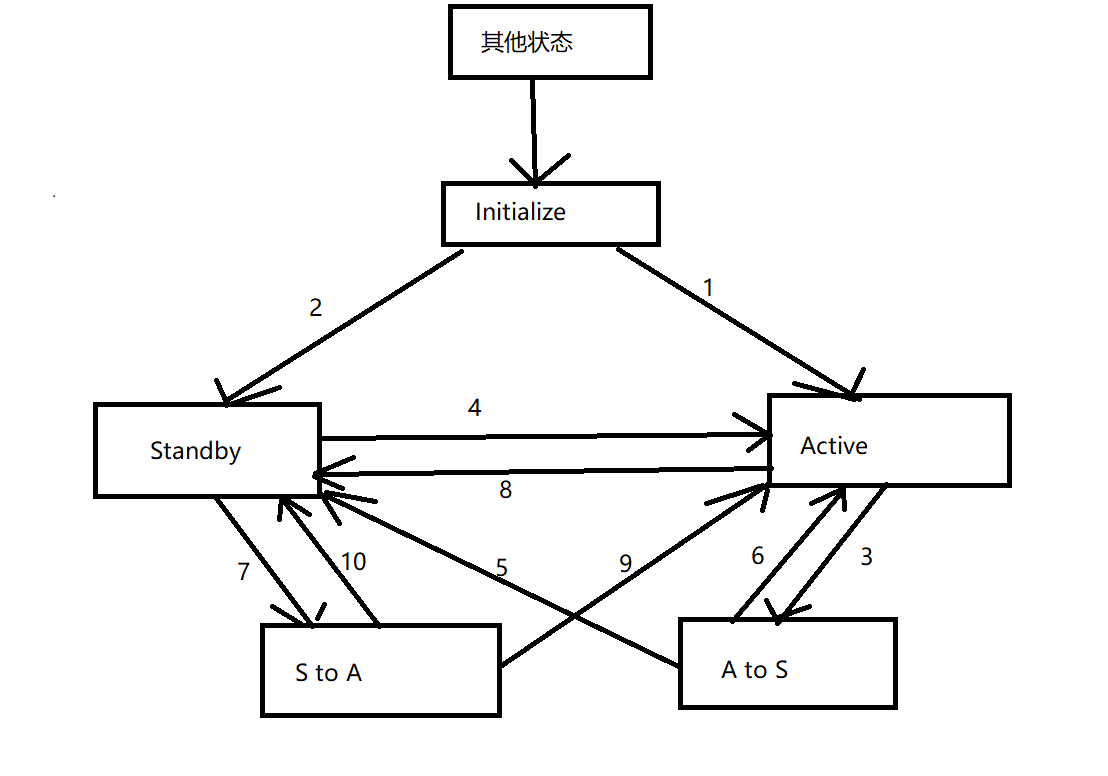
- After the dual hot standby function is enabled, each VGMP group enters the Initialize state.
- When the Active group is enabled, the status of the Active group changes from Initialize to Active.
- When the Standby group is enabled, the status of the Standby group changes from Initialize to Standby.
- When the Interface monitored by the local VGMP group fails, the status switches from Active to A to S, and sends the VGMP request message to the VGMP group of the opposite device.
- The local VGMP group receives the VGMP request message from the opposite end and finds that its priority is high. Then it switches the status from Standby to active and sends the VGMP confirmation message to the VGMP group of the opposite end device.
- When the local VGMP group receives the VGMP confirmation message from the opposite end and confirms that the local end needs to switch the status, the local VGMP group status will be changed from A to S to Standby.
- If the peer VGMP group confirms that the local VGMP group does not need state switching or fails to respond to the local VGMP request message for three consecutive times, the local VGMP group state will be switched from A to S to Active.
- After the Interface monitored by the local VGMP group recovers from failure, if the local VGMP group priority is higher than that of the peer and the preemption function is configured, the status of the local VGMP group will be switched from Standby to S to A, and the VGMP request message will be sent to the peer.
- The local VGMP group receives the VGMP request message from the opposite end, and finds that the opposite end has a high priority, then switches the status from Active to Standby, and sends the VGMP confirmation message to the VGMP group of the opposite device.
- The local VGMP group receives the VGMP confirmation message from the opposite end and confirms that the local end needs to switch the state, then the local VGMP group state is switched from S to A to Active to complete the preemption process.
- If the peer VGMP group confirms that the local VGMP group does not need state switching or fails to respond to the local VGMP request message for three consecutive times, the local VGMP group state will be switched from S to A to Standby.
Working principle of VGMP (in active standby mode)
- Specify devices as Active and Standby
- Set the status of all VRRP backup groups in the VGMP group to the specified Active standby (consistency of VRRP backup group status)
- Active device sends free ARP to refresh MAC address table of switch (guide traffic)
- Send HRP heartbeat message periodically (one second for death and three seconds for death), monitor Active and Standby
Fault detection of VGMP
- For direct connect failures
A. Detect VRRP backup group status
 Application scenario: the firewall service interface works on the third layer, with the upper and lower switches (the second layer)

B. Detect the state of three-layer interface
 Application scenario: the firewall service interface works on three layers, connecting the router up and down
int xxxx
hrp track xxxx

C detect VLAN interface status
 Application scenario: the firewall service interface works on the second layer, connecting the switch up and down (or connecting the router up and down)
vlan xxx
hrp track XXXX
- Non direct connection failure
IP-LINK
BFD

###IP-LINK
 IP link refers to that FW periodically sends a detection message to the designated destination IP and waits for an answer,
To determine if the link has failed.
After FW sends the detection message, no response message is received within three detection cycles (default is 15s),
The current link fails and the IP link status changes to Down. Subsequently,
FW will perform IP link down related follow-up operations, such as dual hot standby active standby switching.
When the link recovers from the fault, FW can receive three consecutive response messages, it is considered that the link fault has been eliminated,
The IP link status changes to Up. In other words, the IP link status does not change to Up immediately after link failure recovery,
Instead, it takes three detection cycles (15s by default) before it changes to Up.
Basic principles of HRP protocol
- HRP protocol realizes backup session table and other state information and key configuration
- HRP message is actually a kind of VGMP message, which is carried in the Data area of VGMP message. There are two encapsulation methods
- The HRP message on the management interface will carry: specify whether to back up automatically or in batches, specify whether to send or reply, and the data type of backup. The two methods are as follows:
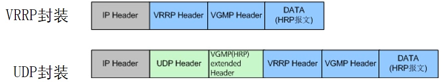
- Two ways of forwarding
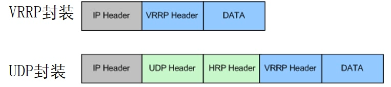
- Encapsulate VRRP, multicast 224.0.0.18, do not need to consider security policy monitoring
- Package UDP, unicast, need to consider security policy monitoring
- When configuring the heartbeat line, you need to consider remote
Backup mode of HRP
- Automatic backup, default
- Manual backup, batch mode (hrp sync config triggers batch backup manually)
- Fast backup for split load sharing
Backup channel status
- When heartbeat ports are configured on both sides of the device, the firewall will judge the physical and protocol status of the heartbeat interface. There are five states in the heartbeat link
- running: normal operation, able to send messages
- ready: normal operation, this interface is a backup channel, not currently used
- peerdown: this section is normal, but the heartbeat message of the opposite end cannot be received
- invaild: the IP address of the unspecified heartbeat address. The heartbeat port works on the second floor
- Down: the physical state and protocol state of the heartbeat interface are down
When there are multiple heart jumpers, which interface is configured first, i.e. which interface's state becomes ready first. When the heartbeat lines at both ends communicate, the interface that becomes ready first becomes running
When the local running interface is down, the second ready interface will replace the down interface to become the running interface of the local device.
The inheritance order is based on the time when it becomes ready, and there is no priority comparison. Just look at the time stamp.
When there are more than one heartbeat at both ends, if the running port at both ends is not a link, it can also communicate normally
heartbeat
- In the dual machine hot standby network, the heartbeat line is the channel for two FW interactive messages to understand the peer status, backup configuration commands and various table items. The interface at both ends of the heartbeat line is usually called "heartbeat interface"
- The heartbeat line mainly delivers the following messages
Heartbeat message (hello message): two FW S send heartbeat messages to each other on a regular basis (default period is 1 second) to detect whether the opposite device is alive
 VGMP message: understand the VGMP group status of the peer equipment, determine whether the current status of the local and peer equipment is stable, and whether a failover is required
 Configuration and table item backup message: used for synchronous configuration command and status information of two FW S
 Heartbeat link detection message: it is used to detect whether the heartbeat port of the opposite equipment can normally receive the messages of the local equipment, and determine whether there is a heartbeat interface that can be used
 Configuration consistency check message: used to check whether the key configurations of two FW S are consistent, such as security policy, NAT, etc
2, Example of firewall hot standby
Network topology
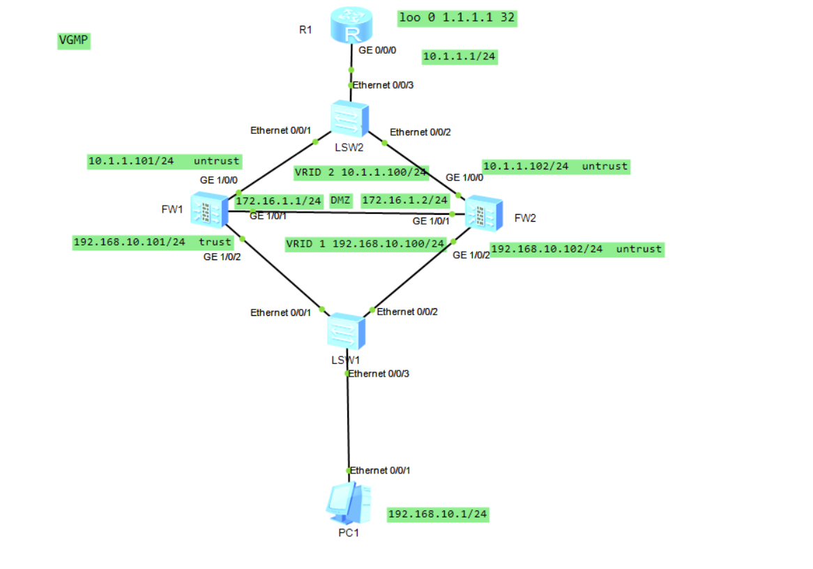
Specific configuration and analysis
Configuration of R1
<Huawei>sys
Enter system view, return user view with Ctrl+Z.
[Huawei]sysname R1
[R1]un in en
Info: Information center is disabled.
[R1]int g0/0/0
[R1-GigabitEthernet0/0/0]ip add 10.1.1.1 24
[R1-GigabitEthernet0/0/0]un sh
Info: Interface GigabitEthernet0/0/0 is not shutdown.
[R1-GigabitEthernet0/0/0]q
[R1]int loo0
[R1-LoopBack0]ip add 1.1.1.1 32
[R1-LoopBack0]q
[R1]ip route-static 192.168.10.0 24 10.1.1.100    //Configure static backhaul routing down
Configuration of FW1
<USG6000V1>sys
Enter system view, return user view with Ctrl+Z.
[USG6000V1]sysname FW1
[FW1]un in en
Info: Saving log files...
Info: Information center is disabled.
[FW1]int g1/0/0
[FW1-GigabitEthernet1/0/0]ip add 10.1.1.101 24
[FW1-GigabitEthernet1/0/0]un sh
Info: Interface GigabitEthernet1/0/0 is not shutdown.
[FW1-GigabitEthernet1/0/0]q
[FW1]int g1/0/1
[FW1-GigabitEthernet1/0/1]ip add 172.16.1.1 24
[FW1-GigabitEthernet1/0/1]un sh
Info: Interface GigabitEthernet1/0/1 is not shutdown.
[FW1-GigabitEthernet1/0/1]q
[FW1]firewall zone untrust //Define interfaces for each area
[FW1-zone-untrust]add int g1/0/0
[FW1-zone-untrust]firewall zone dmz
[FW1-zone-dmz]add int g1/0/1
[FW1-zone-dmz]firewall zone trust
[FW1-zone-trust]add int g1/0/2
[FW1-zone-trust]q
[FW1]ip route-static 0.0.0.0 0.0.0.0 10.1.1.1 //Configure return route up
[FW1]security-policy //Configure security policy
[FW1-policy-security]rule name permit_heat //Define rule name
[FW1-policy-security-rule-permit_heat]source-zone local //Define source area
[FW1-policy-security-rule-permit_heat]destination-zone dmz //Define destination area
[FW1-policy-security-rule-permit_heat]action permit //Action set to allow
[FW1-policy-security-rule-permit_heat]q
[FW1-policy-security]rule name permit_trust_untrust //Configure trust and untrust zone rules
[FW1-policy-security-rule-permit_trust_untrust]source-zone trust
[FW1-policy-security-rule-permit_trust_untrust]destination-zone untrust
[FW1-policy-security-rule-permit_trust_untrust]action permit
[FW1-policy-security-rule-permit_trust_untrust]q
[FW1]int g1/0/2
[FW1-GigabitEthernet1/0/2]ip add 192.168.10.101 24
###Define the VRRP primary group and virtual IP address of the lower interface
[FW1-GigabitEthernet1/0/2]vrrp vrid 1 virtual-ip 192.168.10.100 active
[FW1-GigabitEthernet1/0/2]un sh
Info: Interface GigabitEthernet1/0/2 is not shutdown.
[FW1-GigabitEthernet1/0/2]q
[FW1]int g1/0/0
###Define the VRRP primary group and virtual IP address of the upper interface
[FW1-GigabitEthernet1/0/0]vrrp vrid 2 virtual-ip 10.1.1.100 active
[FW1-GigabitEthernet1/0/0]un sh
Info: Interface GigabitEthernet1/0/0 is not shutdown.
[FW1-GigabitEthernet1/0/0]q
[FW1]hrp int g1/0/1 remote 172.16.1.2 //Configure heartbeat interface
[FW1]hrp enable //Start dual hot standby
Info: NAT IP detect function is disabled.
HRP_S[FW1]hrp auto-sync //Define the hot standby mode of dual computers as automatic backup
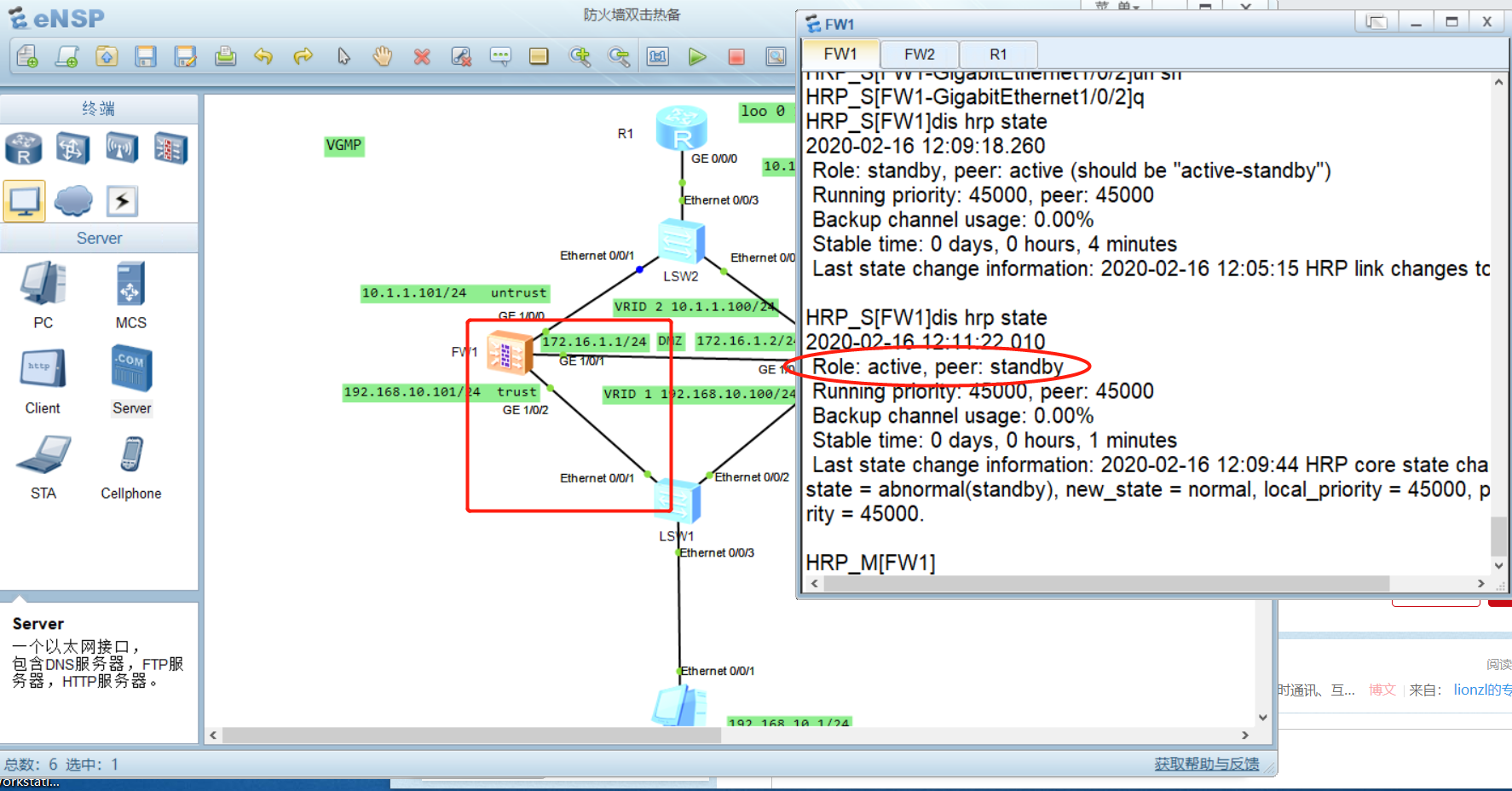
HRP_S[FW1]display hrp state //View dual hot standby status information
2020-02-16 11:25:47.720
Role: standby, peer: unknown
Running priority: 45000, peer: unknown
Backup channel usage: 0.00%
Stable time: 0 days, 0 hours, 0 minutes
Last state change information: 2020-02-16 11:25:11 HRP core state changed, old_
state = initial, new_state = abnormal(standby), local_priority = 45000, peer_pri
ority = unknown.
HRP_S[FW1]dis hrp int //View heartbeat interface status information
2020-02-16 11:26:14.920
GigabitEthernet1/0/1 : negotiation failed
HRP_S[FW1]Configuration of FW2
<USG6000V1>sys
Enter system view, return user view with Ctrl+Z.
[USG6000V1]sysname FW2
[FW2]un in en
Info: Saving log files...
Info: Information center is disabled.
[FW2]int g1/0/0
[FW2-GigabitEthernet1/0/0]ip add 10.1.1.102 24
[FW2-GigabitEthernet1/0/0]un sh
Info: Interface GigabitEthernet1/0/0 is not shutdown.
[FW2-GigabitEthernet1/0/0]q
[FW2]int g1/0/1
[FW2-GigabitEthernet1/0/1]ip add 172.16.1.2 24
[FW2-GigabitEthernet1/0/1]un sh
Info: Interface GigabitEthernet1/0/1 is not shutdown.
[FW2-GigabitEthernet1/0/1]q
[FW2]firewall zone untrust
[FW2-zone-untrust]add int g1/0/0
[FW2-zone-untrust]q
[FW2]firewall zone dmz
[FW2-zone-dmz]add int g1/0/1
[FW2-zone-dmz]firewall zone trust
[FW2-zone-trust]add int g1/0/2
[FW2-zone-trust]q
[FW2]ip route-static 0.0.0.0 0.0.0.0 10.1.1.1
[FW2]security-policy
[FW2-policy-security]rule name permit_heat
[FW2-policy-security-rule-permit_heat]source-zone local
[FW2-policy-security-rule-permit_heat]destination-zone dmz
[FW2-policy-security-rule-permit_heat]action permit
[FW2-policy-security-rule-permit_heat]q
[FW2-policy-security]rule name permit_trust_untrust
[FW2-policy-security-rule-permit_trust_untrust]source-zone trust
[FW2-policy-security-rule-permit_trust_untrust]destination-zone untrust
[FW2-policy-security-rule-permit_trust_untrust]action permit
[FW2-policy-security-rule-permit_trust_untrust]q
[FW2-policy-security]int g1/0/2
[FW2-GigabitEthernet1/0/2]ip add 192.168.10.102 24
###Define the virtual IP address of the lower interface and VRRP as the standby group status
[FW2-GigabitEthernet1/0/2]vrrp vrid 1 virtual-ip 192.168.10.100 standby
[FW2-GigabitEthernet1/0/2]un sh
Info: Interface GigabitEthernet1/0/2 is not shutdown.
[FW2-GigabitEthernet1/0/2]q
[FW2]int g1/0/0
###Define the virtual IP address of the upper interface and VRRP as the standby group status
[FW2-GigabitEthernet1/0/0]vrrp vrid 2 virtual-ip 10.1.1.100 standby
[FW2-GigabitEthernet1/0/0]un sh
Info: Interface GigabitEthernet1/0/0 is not shutdown.
[FW2-GigabitEthernet1/0/0]q
[FW2]hrp int g1/0/1 remote 172.16.1.1
[FW2]hrp enable
Info: NAT IP detect function is disabled.
HRP_S[FW2]hrp auto-sync
HRP_S[FW2]dis hrp state
2020-02-16 11:34:15.410
 Role: standby, peer: active
 Running priority: 45000, peer: 45000
 Backup channel usage: 0.02%
 Stable time: 0 days, 0 hours, 0 minutes
 Last state change information: 2020-02-16 11:34:08 HRP core state changed, old_
state = abnormal(active), new_state = normal, local_priority = 45000, peer_prior
ity = 45000.

HRP_S[FW2]dis hrp int
2020-02-16 11:34:28.650
             GigabitEthernet1/0/1 : running

HRP_S[FW2]
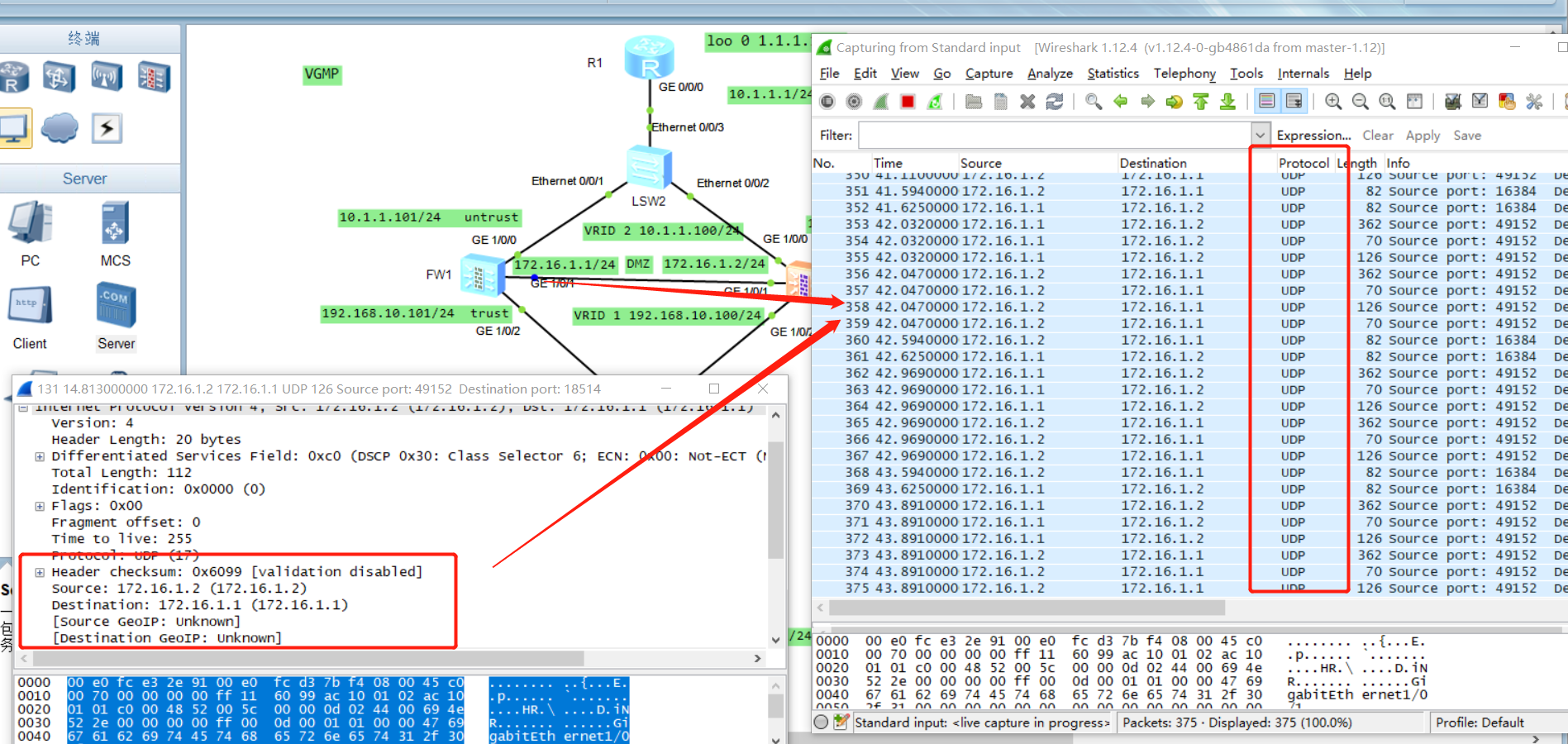
experimental verification
- Grab the packet at the heartbeat line, and its protocol is UDP
- By the loopback address of pingR1 at PC1
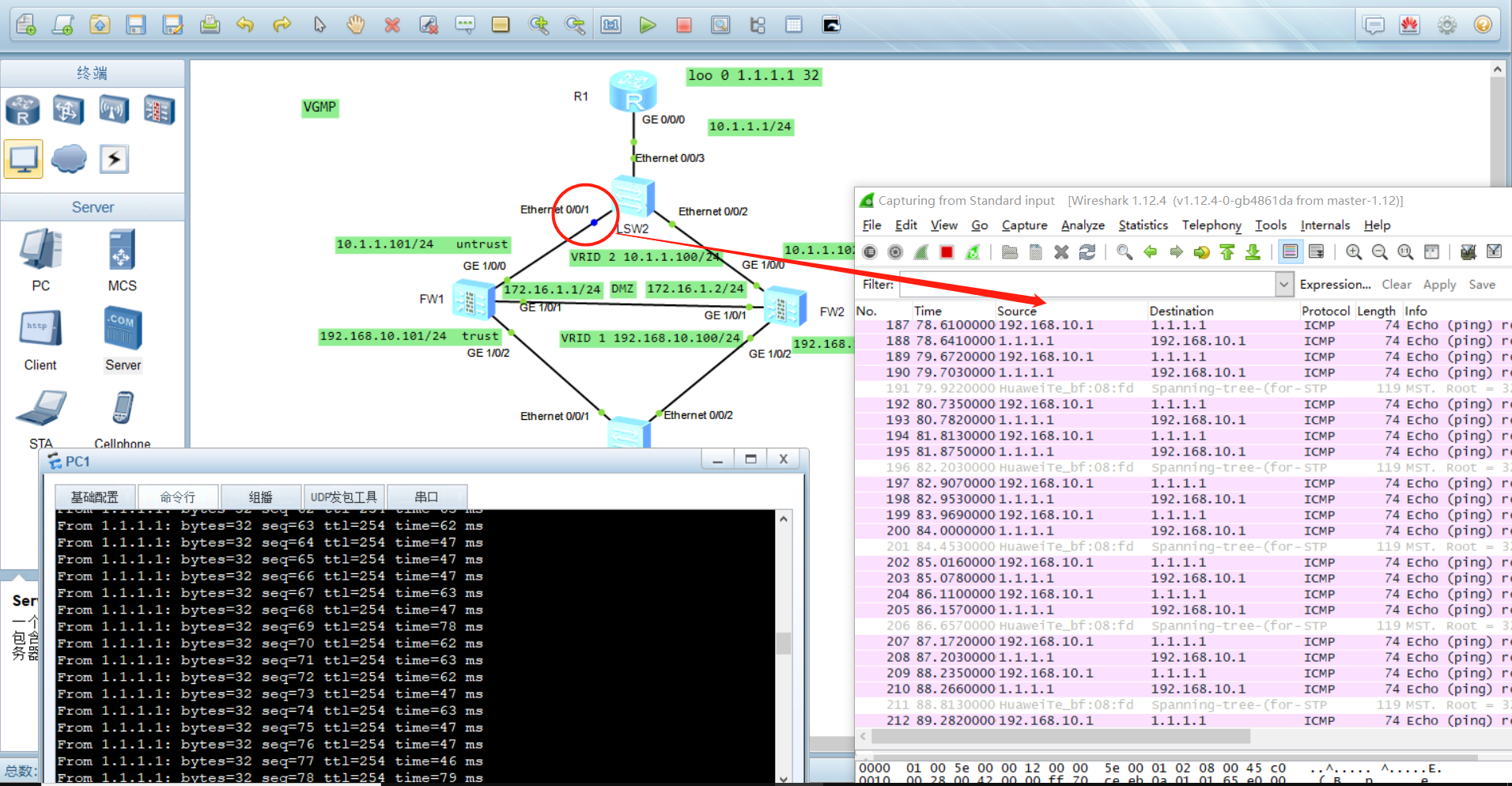
- Simulate the failover, down the connector on FW1, and then Ping R1 from pc1pingR1
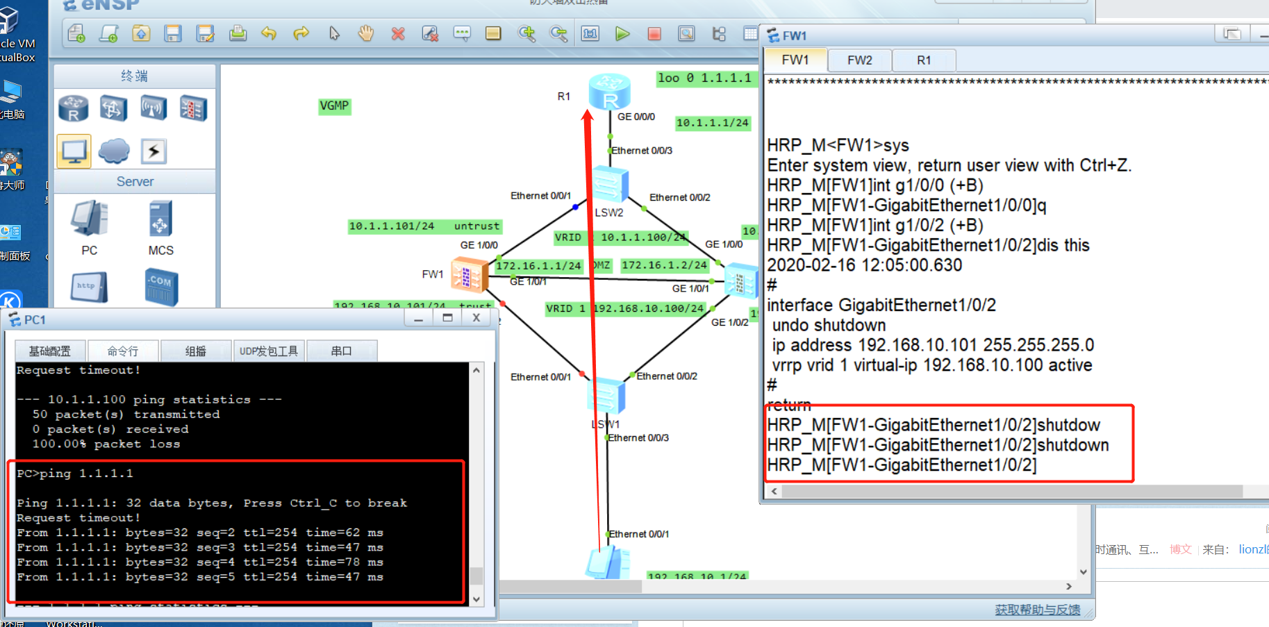
- After recovering the fault, fw1 changes from standby to active due to preemption mechanism