Design of temperature and humidity display in cabin based on STM32
This design uses the STM32F103ZET6 elite development board of punctual atom.
Data acquisition: the temperature and humidity sensor uses DHT11 to collect humidity and DS18B20 to collect temperature.
Display: the display part is divided into TFT-LCD display and upper computer Labview display.
This design is only for learning and communication, and does not involve commercial purposes.
Design Introduction
Constant temperature and humidity system is widely used, mainly in drug production workshop. Intelligent equipment is used to keep the temperature and humidity in the workshop within a very small range. Generally speaking, it is air conditioning system and air purification system.
In the microbiology laboratory, the incubator is also a constant temperature and humidity system. It is necessary to detect temperature and humidity everywhere in life, and carry out corresponding operations through the measured data.
Tip: the following is the main content of this article. The following cases can be used for reference
1, Design requirements
(1) It is designed on the basis of STM32F103 development board.
(2) DS18B20 temperature sensor is used to realize temperature acquisition; Use DHT11 temperature and humidity sensor to measure humidity data.
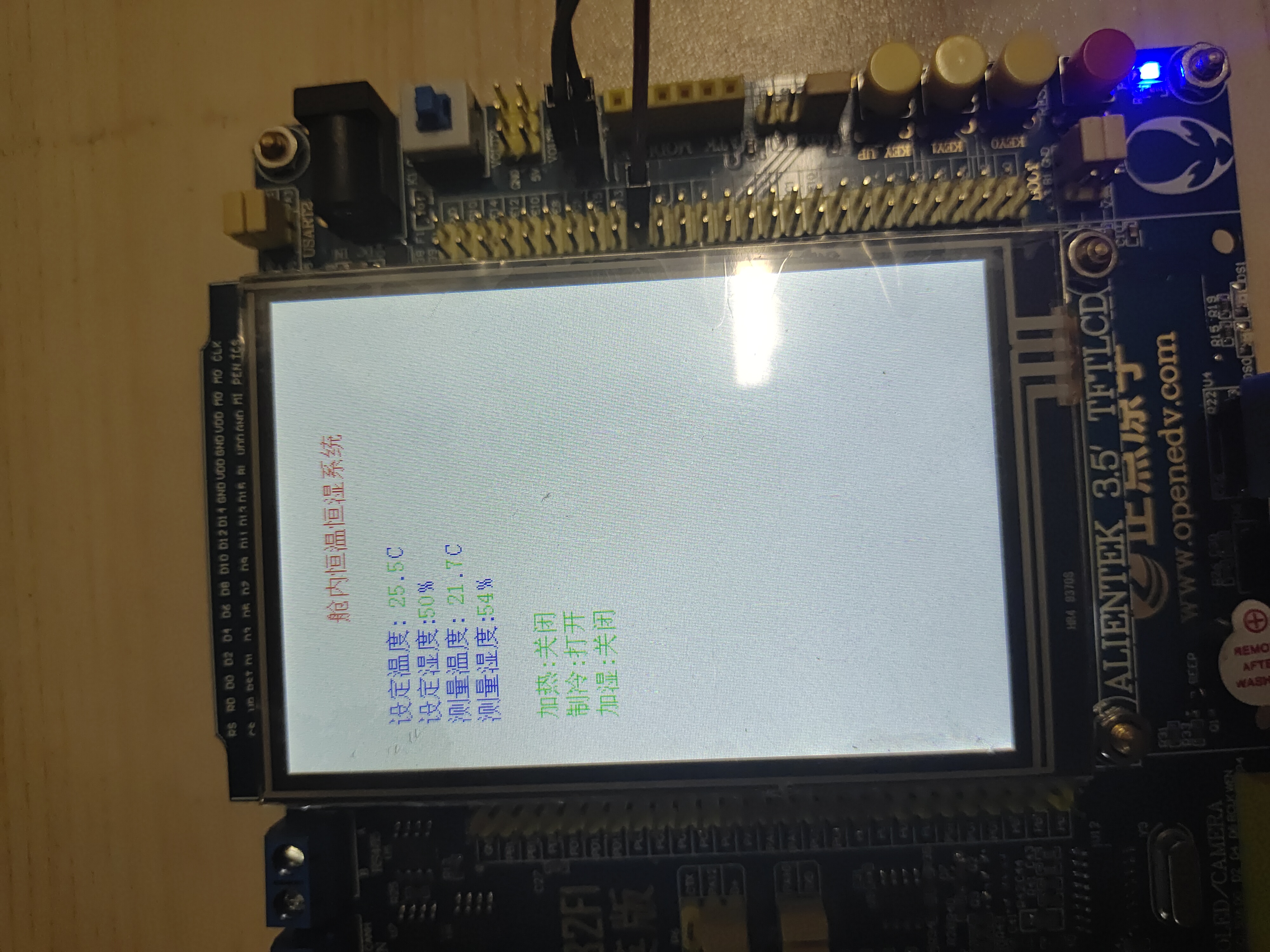
(3) Use the LCD of the development board to display the set temperature, measured temperature and humidity.
(4) Use the built-in keys of the development board to modify the set temperature.
(5) The heating, refrigeration and humidification systems are controlled by relays, and the current working status of each system is displayed on the LCD screen.
(6) Use the serial port to upload the data to the upper computer.
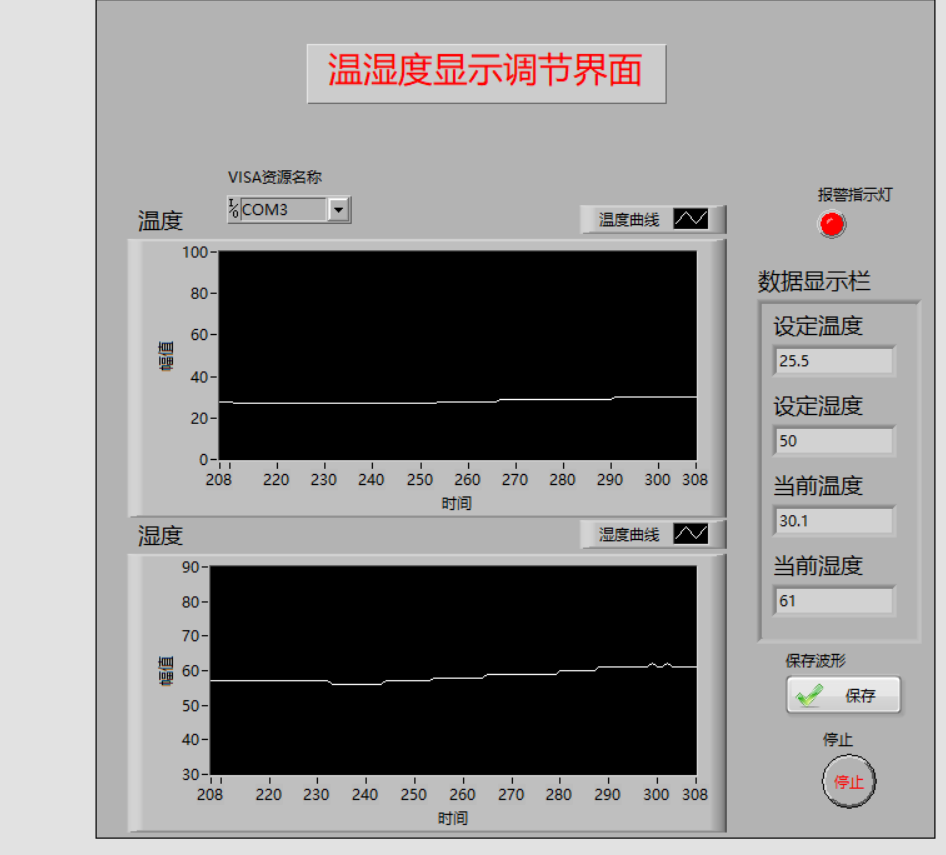
(7) The upper computer uses LabVIEW to compile the display control interface, including the current temperature, set temperature, current humidity, set humidity, temperature and humidity alarm lamp and temperature and humidity time curve.
(8) The upper computer keeps the temperature and humidity data in the hard disk file.
2, Design steps
1.DS18B20 temperature acquisition
(1) Introduction: DS18B20 is a commonly used digital temperature sensor. Its output is digital signal. It has the characteristics of small volume, low hardware overhead, strong anti-interference ability and high precision. [1] DS18B20 digital temperature sensor has convenient wiring and can be applied to a variety of occasions after packaging, such as pipeline type, threaded type, magnet adsorption type, stainless steel packaging type. There are a variety of models, including LTM8877, LTM8874 and so on. The appearance is mainly changed according to different applications. The packaged DS18B20 can be used for various non limit temperature occasions, such as cable trench temperature measurement, blast furnace water circulation temperature measurement, boiler temperature measurement, machine room temperature measurement, agricultural greenhouse temperature measurement, clean room temperature measurement, ammunition depot temperature measurement and so on. The utility model has the advantages of wear resistance, collision resistance, small volume, convenient use and various packaging forms, and is suitable for the field of digital temperature measurement and control of various narrow space equipment.
(2) Features: the unique one-wire interface only needs one port line communication multipoint capability, which simplifies the distributed temperature sensing application without external components. The data bus can be used for power supply. The voltage range is 3.0 V to 5.5 V without standby power supply. The measurement temperature range is - 55 ° C to + 125 ℃. Fahrenheit is equivalent to - 67 ° f to 257 ° F. The accuracy is ± 0.5 ° C in the range of - 10 ° C to + 85 ° C. The programmable resolution of the temperature sensor is 9 ~ 12 bits, the temperature is converted to 12 bit digital format, and the maximum value is 750 milliseconds. The user-defined nonvolatile temperature alarm settings can be used in thermostatic control, industrial systems, consumer electronics thermometers, or any thermal sensing system.
(3) Control process:
initialization
① First set the data line to high level "1".
② Delay (the time requirement is not very strict, but it should be as short as possible)
③ Pull the data line to low level "0".
④ Delay 750 microseconds (this time can range from 480 to 960 microseconds).
⑤ Pull the data line to high level "1".
⑥ Delay waiting (if the initialization is successful, a low level "0" returned by DS18B20 will be generated within 15 to 60 microseconds. Its existence can be determined according to this state, but it should be noted that it cannot wait indefinitely, otherwise the program will enter an endless loop, so timeout control should be carried out).
⑦ If the CPU needs to delay after reading the low level "0" on the data line, the delay time shall be at least 480 microseconds from the issued high level (from the time in step (5)).
⑧ Pull the data line to high level "1" again and end.
Write operation
① The data line is set to low level "0" first.
② The time delay is determined as 15 microseconds.
③ Send bytes in order from low to high (only one bit at a time).
④ The delay time is 45 microseconds.
⑤ Pull the data cable to high level.
⑥ Repeat the operations from ① to ⑥ until all bytes are sent.
⑦ Finally, pull up the data cable.
Read operation
① Pull the data cable up "1".
② Delay 2 microseconds.
③ Pull the data cable down "0".
④ Delay 3 microseconds.
⑤ Pull the data cable up "1".
⑥ Delay 5 microseconds.
⑦ Read the status of the data line, get a status bit, and process the data.
⑧ Delay 60 microseconds.
(4) Communication with MCU: serial transmission to CPU by one-line bus and CRC check code at the same time.
The code is as follows (DS18B20):
DS18B20.h file
#ifndef __DS18B20_H
#define __DS18B20_H
#include "sys.h"
//IO direction setting
#define DS18B20_IO_IN()  {GPIOF->CRH&=0XFFFF0FFF;GPIOF->CRH|=8<<12;}
#define DS18B20_IO_OUT() {GPIOF->CRH&=0XFFFF0FFF;GPIOF->CRH|=3<<12;}
IO Operation function
#define 	 DS18B20_DQ_OUT PFout(11) / / data port 	 PA0
#define 	 DS18B20_ DQ_ In pfin (11) / / data port 	 PA0

u8 DS18B20_Init(void);//Initialize DS18B20
short DS18B20_Get_Temp(void);//Get temperature
void DS18B20_Start(void);//Start temperature conversion
void DS18B20_Write_Byte(u8 dat);//Write a byte
u8 DS18B20_Read_Byte(void);//Read a byte
u8 DS18B20_Read_Bit(void);//Read one bit
u8 DS18B20_Check(void);//Detect the presence of DS18B20
void DS18B20_Rst(void);//Reset DS18B20
#endif
DS18B20.c file
#include "ds18b20.h"
#include "delay.h"
//Reset DS18B20
void DS18B20_Rst(void)
{
	DS18B20_IO_OUT(); 	//SET PG11 OUTPUT
    DS18B20_DQ_OUT=0; 	//Pull down DQ
    delay_us(750);    	//Pull down 750us
    DS18B20_DQ_OUT=1; 	//DQ=1
	delay_us(15);     	//15US
}
//Waiting for a response from DS18B20
//Return 1: the existence of DS18B20 is not detected
//Return 0: exists
u8 DS18B20_Check(void)
{
	u8 retry=0;
	DS18B20_IO_IN();	//SET PG11 INPUT
    while (DS18B20_DQ_IN&&retry<200)
	{
		retry++;
		delay_us(1);
	};
	if(retry>=200)return 1;
	else retry=0;
    while (!DS18B20_DQ_IN&&retry<240)
	{
		retry++;
		delay_us(1);
	};
	if(retry>=240)return 1;
	return 0;
}
//Read a bit from DS18B20
//Return value: 1 / 0
u8 DS18B20_Read_Bit(void)
{
    u8 data;
	DS18B20_IO_OUT();	//SET PG11 OUTPUT
    DS18B20_DQ_OUT=0;
	delay_us(2);
    DS18B20_DQ_OUT=1;
	DS18B20_IO_IN();	//SET PG11 INPUT
	delay_us(12);
	if(DS18B20_DQ_IN)data=1;
    else data=0;
    delay_us(50);
    return data;
}
//Read a byte from DS18B20
//Return value: read data
u8 DS18B20_Read_Byte(void)
{
    u8 i,j,dat;
    dat=0;
	for (i=1;i<=8;i++)
	{
        j=DS18B20_Read_Bit();
        dat=(j<<7)|(dat>>1);
    }
    return dat;
}
//Write a byte to DS18B20
//dat: bytes to write
void DS18B20_Write_Byte(u8 dat)
 {
    u8 j;
    u8 testb;
	DS18B20_IO_OUT();	//SET PG11 OUTPUT;
    for (j=1;j<=8;j++)
	{
        testb=dat&0x01;
        dat=dat>>1;
        if (testb)
        {
            DS18B20_DQ_OUT=0;	// Write 1
            delay_us(2);
            DS18B20_DQ_OUT=1;
            delay_us(60);
        }
        else
        {
            DS18B20_DQ_OUT=0;	// Write 0
            delay_us(60);
            DS18B20_DQ_OUT=1;
            delay_us(2);
        }
    }
}
//Start temperature conversion
void DS18B20_Start(void)
{
    DS18B20_Rst();
	DS18B20_Check();
    DS18B20_Write_Byte(0xcc);	// skip rom
    DS18B20_Write_Byte(0x44);	// convert
}

//Initialize the IO port DQ of DS18B20 and detect the existence of DS at the same time
//Return 1: does not exist
//Return 0: exists
u8 DS18B20_Init(void)
{
 	GPIO_InitTypeDef  GPIO_InitStructure;

 	RCC_APB2PeriphClockCmd(RCC_APB2Periph_GPIOF, ENABLE);	 //Enable PORTG port clock

 	GPIO_InitStructure.GPIO_Pin = GPIO_Pin_11;				//PORTG.11 push pull output
 	GPIO_InitStructure.GPIO_Mode = GPIO_Mode_Out_PP;
 	GPIO_InitStructure.GPIO_Speed = GPIO_Speed_50MHz;
 	GPIO_Init(GPIOF, &GPIO_InitStructure);

 	GPIO_SetBits(GPIOF,GPIO_Pin_11);    //Output 1

	DS18B20_Rst();

	return DS18B20_Check();
}
//Get the temperature value from ds18b20
//Accuracy: 0.1C
//Return value: temperature value (- 550 ~ 1250)
short DS18B20_Get_Temp(void)
{
    u8 temp;
    u8 TL,TH;
	short tem;
    DS18B20_Start ();  			// ds1820 start convert
    DS18B20_Rst();
    DS18B20_Check();
    DS18B20_Write_Byte(0xcc);	// skip rom
    DS18B20_Write_Byte(0xbe);	// convert
    TL=DS18B20_Read_Byte(); 	// LSB
    TH=DS18B20_Read_Byte(); 	// MSB

    if(TH>7)
    {
        TH=~TH;
        TL=~TL;
        temp=0;					//The temperature is negative
    }else temp=1;				//The temperature is positive
    tem=TH; 					//Get the top eight
    tem<<=8;
    tem+=TL;					//Get the bottom eight
    tem=(float)tem*0.625;		//transformation
	if(temp)return tem; 		//Return temperature value
	else return -tem;
}
2.DHT11 temperature and humidity collection
(1) DHT11 digital temperature and humidity sensor is a temperature and humidity composite sensor with calibrated digital signal output. It applies special digital module acquisition technology and temperature and humidity sensing technology to ensure that the product has high reliability and excellent long-term stability. The sensor includes a resistive humidity sensing element and an NTC temperature measuring element, and is connected with a high-performance 8-bit single chip microcomputer. Therefore, the product has the advantages of excellent quality, ultra fast response, strong anti-interference ability and high cost performance. Each DHT11 sensor is calibrated in an extremely accurate humidity calibration chamber. Calibration coefficients are stored in OTP memory in the form of program, and these calibration coefficients are called during the processing of detection signals inside the sensor. Single line serial interface makes system integration simple and fast. Ultra small size and low power consumption make it the best choice in this kind of applications and harsh applications. The product is packaged with 4-pin single row pins, which is convenient for connection.
(2) DHT11 resolution: the resolutions are 8b (temperature) and 8b (humidity) respectively.
(3) DHT11 serial communication: the communication and synchronization between MCU and DHT11 adopts single bus data format. One communication time is about 4ms, and the data is divided into decimal part and integer part. A complete public data transmission is 40b, with high bit first out.
(4) Communication process with MCU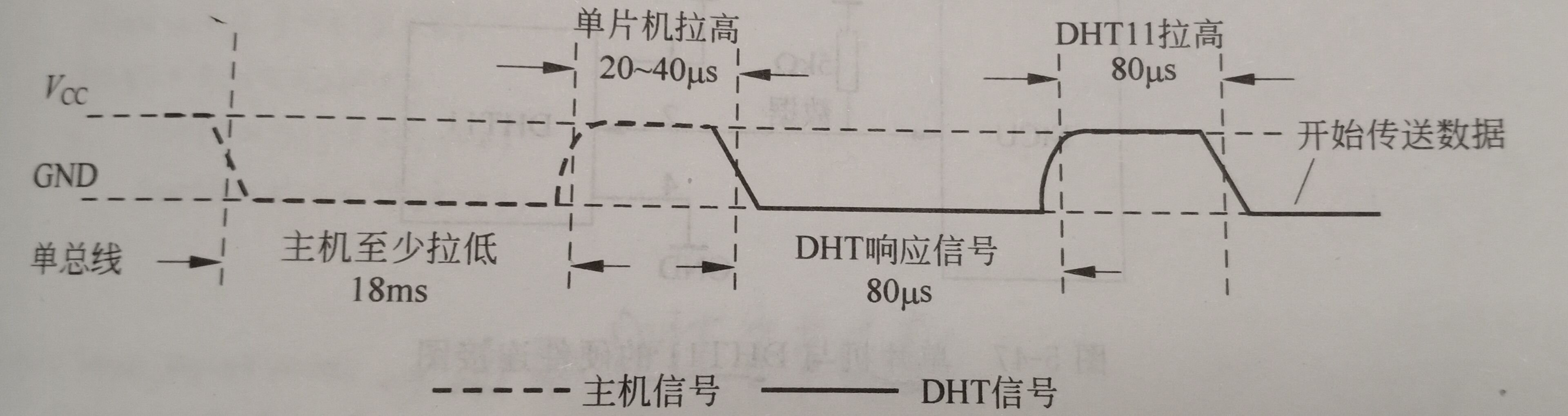
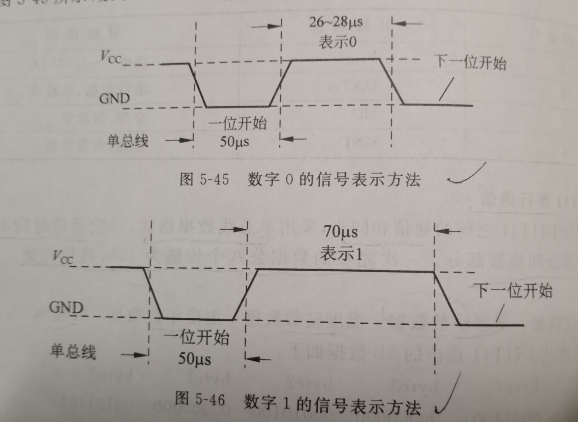
(5) Each bit of data sent by the DHT11 sensor has a 50us low-level time slot
At first, the length of the high level determines whether the data bit is 0 or 1.
 The code is as follows (DHT11):
DHT11.h file
#ifndef __DHT11_H
#define __DHT11_H
#include "sys.h"
//IO direction setting
#define DHT11_IO_IN()  {GPIOG->CRH&=0XFFFF0FFF;GPIOG->CRH|=8<<12;}
#define DHT11_IO_OUT() {GPIOG->CRH&=0XFFFF0FFF;GPIOG->CRH|=3<<12;}
IO Operation function
#define 	 DHT11_DQ_OUT PGout(11) / / data port 	 PA0
#define 	 DHT11_ DQ_ In pgin (11) / / data port 	 PA0


u8 DHT11_Init(void);//Initialize DHT11
u8 DHT11_Read_Data(u8 *temp,u8 *humi);//Read temperature and humidity
u8 DHT11_Read_Byte(void);//Read a byte
u8 DHT11_Read_Bit(void);//Read one bit
u8 DHT11_Check(void);//Detect the presence of DHT11
void DHT11_Rst(void);//Reset DHT11
#endif
DHT11.c file
#include "dht11.h"
#include "delay.h"
//Reset DHT11
void DHT11_Rst(void)
{
	DHT11_IO_OUT(); 	//SET OUTPUT
    DHT11_DQ_OUT=0; 	//Pull down DQ
    delay_ms(20);    	//Pull down for at least 18ms
    DHT11_DQ_OUT=1; 	//DQ=1
	delay_us(30);     	//The main engine is pulled up by 20~40us
}
//Waiting for a response from DHT11
//Return 1: the existence of DHT11 is not detected
//Return 0: exists
u8 DHT11_Check(void)
{
	u8 retry=0;
	DHT11_IO_IN();//SET INPUT
    while (DHT11_DQ_IN&&retry<100)//DHT11 will pull down 40~80us
	{
		retry++;
		delay_us(1);
	};
	if(retry>=100)return 1;
	else retry=0;
    while (!DHT11_DQ_IN&&retry<100)//After DHT11 is pulled down, it will be pulled up again by 40~80us
	{
		retry++;
		delay_us(1);
	};
	if(retry>=100)return 1;
	return 0;
}
//Read a bit from DHT11
//Return value: 1 / 0
u8 DHT11_Read_Bit(void)
{
 	u8 retry=0;
	while(DHT11_DQ_IN&&retry<100)//Wait for low level
	{
		retry++;
		delay_us(1);
	}
	retry=0;
	while(!DHT11_DQ_IN&&retry<100)//Wait for high level
	{
		retry++;
		delay_us(1);
	}
	delay_us(40);//Wait 40us
	if(DHT11_DQ_IN)return 1;
	else return 0;
}
//Read a byte from DHT11
//Return value: read data
u8 DHT11_Read_Byte(void)
{
    u8 i,dat;
    dat=0;
	for (i=0;i<8;i++)
	{
   		dat<<=1;
	    dat|=DHT11_Read_Bit();
    }
    return dat;
}
//Read data from DHT11 once
//temp: temperature value (range: 0 ~ 50 °)
//humi: humidity value (range: 20% ~ 90%)
//Return value: 0, normal; 1. Reading failed
u8 DHT11_Read_Data(u8 *temp,u8 *humi)
{
 	u8 buf[5];
	u8 i;
	DHT11_Rst();
	if(DHT11_Check()==0)
	{
		for(i=0;i<5;i++)//Read 40 bit data
		{
			buf[i]=DHT11_Read_Byte();
		}
		if((buf[0]+buf[1]+buf[2]+buf[3])==buf[4])
		{
			*humi=buf[0];
			*temp=buf[2];
		}
	}else return 1;
	return 0;
}
//Initialize the IO port DQ of DHT11 and detect the existence of DHT11
//Return 1: does not exist
//Return 0: exists
u8 DHT11_Init(void)
{
 	GPIO_InitTypeDef  GPIO_InitStructure;

 	RCC_APB2PeriphClockCmd(RCC_APB2Periph_GPIOG, ENABLE);	 //Enable PG port clock

 	GPIO_InitStructure.GPIO_Pin = GPIO_Pin_11;				 //PG11 port configuration
 	GPIO_InitStructure.GPIO_Mode = GPIO_Mode_Out_PP; 		 //Push pull output
 	GPIO_InitStructure.GPIO_Speed = GPIO_Speed_50MHz;
 	GPIO_Init(GPIOG, &GPIO_InitStructure);				 //Initialize IO port
 	GPIO_SetBits(GPIOG,GPIO_Pin_11);						 //PG11 output high

	DHT11_Rst();  //Reset DHT11
	return DHT11_Check();//Waiting for a response from DHT11
}
3.TFT-LCD
The LCD uses the 3.5-inch display provided by the punctual atom. Since the LCD program is too large, only some main programs are shown below.
//Displays a number. If the high order is 0, it will not be displayed
//x. Y: starting point coordinates
//len: number of digits
//Size: font size
//Color: color
//num: value (0 ~ 4294967295);
void LCD_ShowNum(u16 x,u16 y,u32 num,u8 len,u8 size)
{
	u8 t,temp;
	u8 enshow=0;
	for(t=0;t<len;t++)
	{
		temp=(num/LCD_Pow(10,len-t-1))%10;
		if(enshow==0&&t<(len-1))
		{
			if(temp==0)
			{
				LCD_ShowChar(x+(size/2)*t,y,' ',size,0);
				continue;
			}else enshow=1;

		}
	 	LCD_ShowChar(x+(size/2)*t,y,temp+'0',size,0);
	}
}
//display string
//x. Y: starting point coordinates
//width,height: area size
//Size: font size
//*p: String start address
void LCD_ShowString(u16 x,u16 y,u16 width,u16 height,u8 size,u8 *p)
{
	u8 x0=x;
	width+=x;
	height+=y;
    while((*p<='~')&&(*p>=' '))//Judge whether it is an illegal character!
    {
        if(x>=width){x=x0;y+=size;}
        if(y>=height)break;//sign out
        LCD_ShowChar(x,y,*p,size,0);
        x+=size/2;
        p++;
    }
}
4. Main program
#include "stm32f10x.h"                  // Device header
#include "sys.h"
#include "delay.h"
#include "usart.h"
#include "led.h"
#include "lcd.h"
#include "key.h"
#include "usmart.h"
#include "malloc.h"
#include "sdio_sdcard.h"
#include "w25qxx.h"
#include "ff.h"
#include "exfuns.h"
#include "text.h"
#include "dht11.h"
#include "ds18b20.h"
#include "relay.h"

u8 H = 50;	//Set humidity defaults
short T = 255;	//Set temperature defaults

 int main(void)
 {
	u8 key1;
	u8 fontx[2];//gbk code
	u8 t=0;
	u8 temperature1;
	u8 humidity;
	short temperature;

	delay_init();	    	 //Delay function initialization
  NVIC_PriorityGroupConfig(NVIC_PriorityGroup_2);//Set the interrupt priority group as 2: 2-bit preemption priority and 2-bit response priority
	uart_init(115200);	 	//The serial port is initialized to 115200
 	usmart_dev.init(72);		//Initialize USMART
	KEY_Init();						//Key interrupt initialization
 	LED_Init();		  			//Initialize the hardware interface to the LED
	LCD_Init();			   		//Initialize LCD
	W25QXX_Init();				//Initialize W25Q128
 	my_mem_init(SRAMIN);		//Initialize internal memory pool
	exfuns_init();				//Request memory for fatfs related variables
 	f_mount(fs[0],"0:",1); 		//Mount SD card
 	f_mount(fs[1],"1:",1); 		//Mount FLASH
	while(font_init()) 			//Check font
	{
		LCD_ShowString(30,110,200,16,16,"Font Update Success!   ");
		delay_ms(1500);
		LCD_Clear(WHITE);//Clear screen
	}
while(DHT11_Init())	//DHT11 initialization
	{
		LCD_ShowString(30,130,200,16,16,"DHT11 Error");
		delay_ms(200);
		LCD_Fill(30,130,239,130+16,WHITE);
 		delay_ms(200);
	}
	 while(DS18B20_Init())	//DS18B20 initialization
	{
		LCD_ShowString(30,130,200,16,16,"DS18B20 Error");
		delay_ms(200);
		LCD_Fill(30,130,239,130+16,WHITE);
 		delay_ms(200);
	}
//Interface display part
	POINT_COLOR=RED;
	Show_Str(100,30,200,16,"Cabin constant temperature and humidity system",16,0);
	POINT_COLOR=BLUE;
	Show_Str(30,70,200,16,"setting temperature:   . C",16,0);
	Show_Str(30,90,200,16,"Set humidity:  %",16,0);
	Show_Str(30,110,200,16,"Measuring temperature:   . C",16,0);
	Show_Str(30,130,200,16,"Measure humidity:  %",16,0);
 	POINT_COLOR=GREEN;
	Show_Str(30,170,200,16,"heating:",16,0);
	Show_Str(30,190,200,16,"refrigeration:",16,0);
	Show_Str(30,210,200,16,"humidification:",16,0);
	while(1)
	{
 		if(t%10==0)			//Read every 100ms
		{
			DHT11_Read_Data(&temperature1,&humidity);	//Read the temperature and humidity value
			temperature=DS18B20_Get_Temp();
			//Print data to serial port
			printf("\r\n %d.%d C,%d RH,%d.%d C,%d RH \r\n",T/10,T%10,H,temperature/10,temperature%10,humidity);
			delay_ms(10);
			//Read the key value, and then change the set value
			key1=KEY_Scan(0);
			switch(key1){
				case(1):H++;break;
				case(2):T++;break;
				case(3):T--;break;
			}
			//Control heating and cooling
			if(temperature>(T)){
				Show_Str(30+40,170,200,16,"open",16,0);
				GPIO_SetBits(GPIOD,GPIO_Pin_7);	//Turn on the heating switch
			}else{
				Show_Str(30+40,170,200,16,"close",16,0);
				GPIO_ResetBits(GPIOD,GPIO_Pin_7);	//Turn off the heating switch
			}

			if(temperature<(T)){
				Show_Str(30+40,190,200,16,"open",16,0);
				GPIO_SetBits(GPIOD,GPIO_Pin_8);	//Turn on the refrigeration switch
			}else{
				Show_Str(30+40,190,200,16,"close",16,0);
				GPIO_ResetBits(GPIOD,GPIO_Pin_8);	//Turn off the refrigeration switch
			}

			//Controlled humidification
			if(humidity<H){
				Show_Str(30+40,210,200,16,"open",16,0);
				GPIO_SetBits(GPIOD,GPIO_Pin_9);	//Turn on the humidification switch
			}else{
				Show_Str(30+40,210,200,16,"close",16,0);
				GPIO_ResetBits(GPIOD,GPIO_Pin_9);	//Turn off the humidification switch
			}

			//Temperature display
			if(temperature<0)
			{
				LCD_ShowChar(30+40,150,'-',16,0);			//Show negative sign
				temperature=-temperature;					//Turn to positive
			}else LCD_ShowChar(30+40,150,' ',16,0);			//Remove the minus sign
			LCD_ShowNum(30+70+8,110,temperature/10,2,16);	//Show positive part
   		LCD_ShowNum(30+70+32,110,temperature%10,1,16);	//Display decimal part
			LCD_ShowNum(30+70,130,humidity,2,16);		//Display humidity

			LCD_ShowNum(30+70+8,70,T/10,2,16);	//Display the positive part of the set temperature
   		LCD_ShowNum(30+70+32,70,T%10,1,16);	//Display the decimal part of the set temperature
			LCD_ShowNum(30+70,90,H,2,16);		//Display set humidity
		}
	 delay_ms(10);
	 t++;
	 if(t==20)
	 {
		 t=0;
		 LED0=!LED0;
	 }
	}
}
The main program uses small lights, buttons, mounting SD and so on, which will not be repeated.
5. Host computer design
(1) How to communicate with the lower computer: UART serial port is used for communication, and the lower computer prints the temperature and humidity read to the serial port through printf() function.
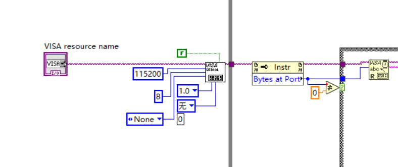
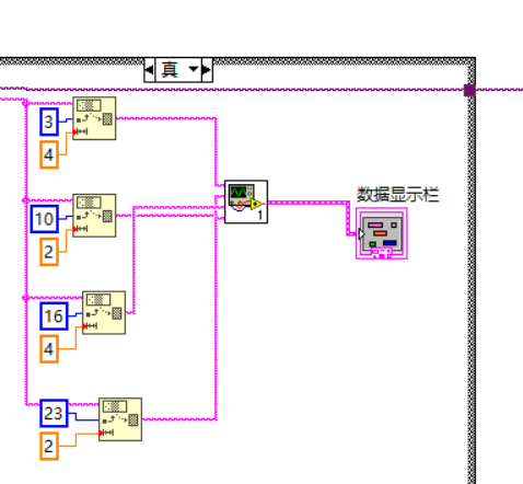
(2) How to deal with the received data: labview intercepts the corresponding data of the received data by intercepting the string function, and then saves it to the cluster.
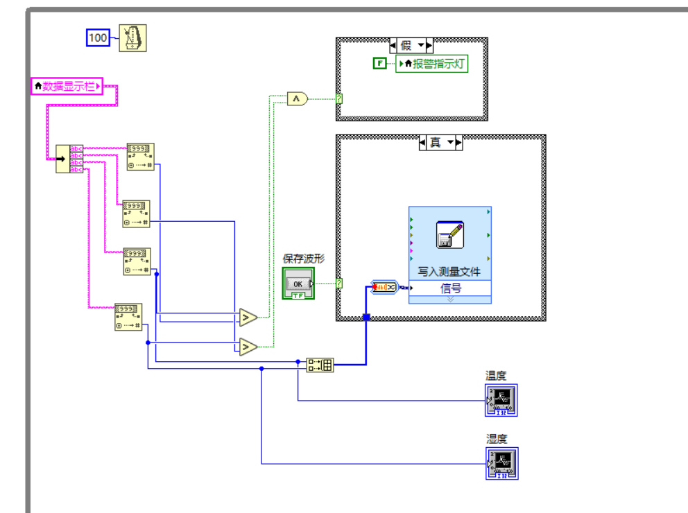
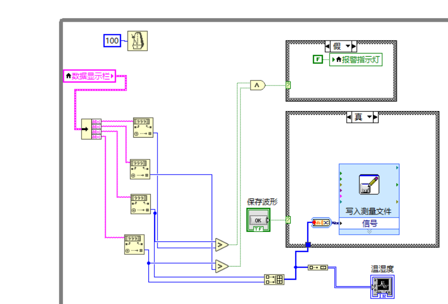
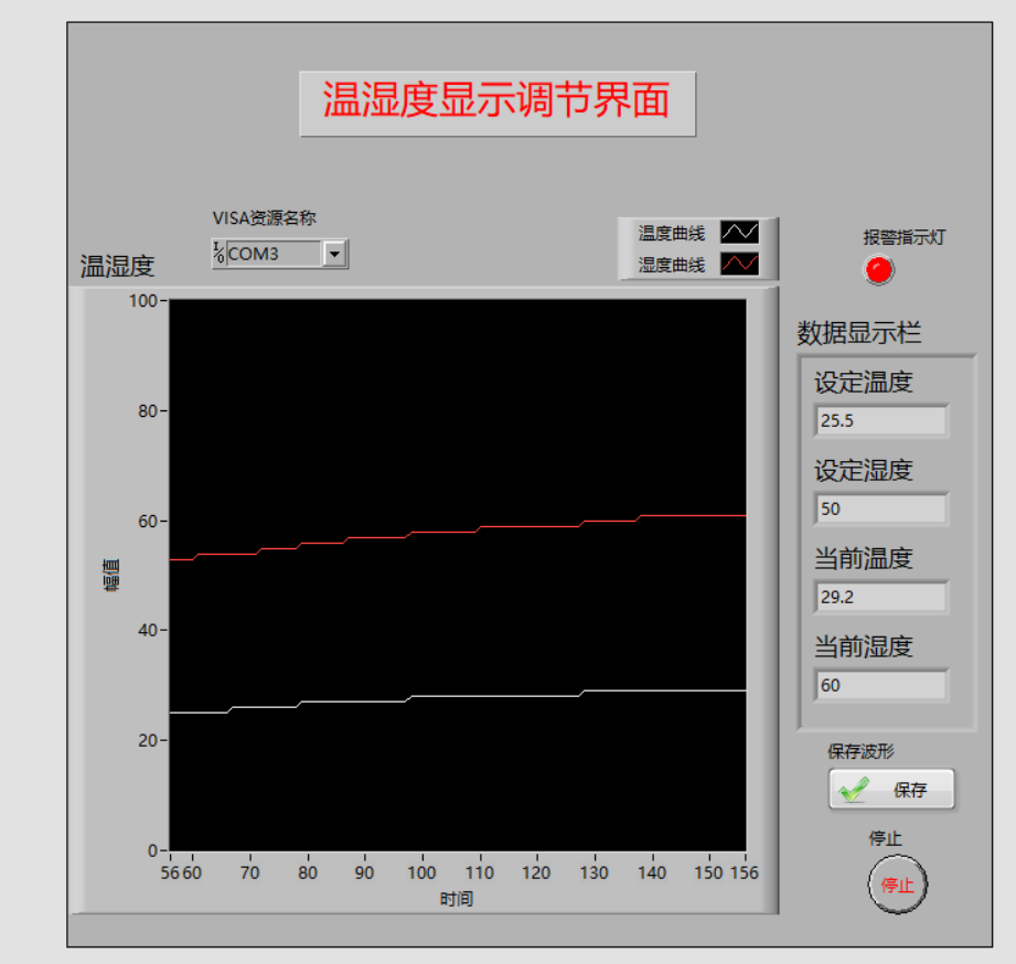
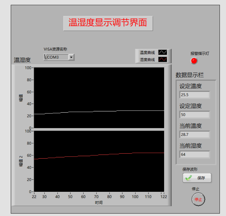
(3) How to display temperature and humidity curve: three display programs are designed this time. The first uses two waveform charts to display temperature and humidity curves respectively; The second uses a waveform chart to display two curves at the same time; The third uses a waveform chart and is displayed in a grid.
6. Achievement display
(1) Lower computer display
(2) Upper computer display
① Two waveform chart displays
② A waveform chart shows two curves
③ A waveform chart displays two curves in a grid
summary
This design mainly aims at how to carry out multi data communication between MCU and host computer, and mainly adopts the methods of string sending and string interception; When STM32 single chip microcomputer is collecting multiple data, it should be noted that if port 1-6 is used to read data, CRL register should be configured, CRH register should be configured when port 7-12 is used to read data, and MODE register should be configured if it is F4 development board. The difficulty of this design is general. Interested friends can innovate their own design.
Program connection
Link: https://pan.baidu.com/s/1NfpzWLy2M4SHVzIJrNREjw
Extraction code: d2jn