Web Real-Time Communication (WebRTC) consists of a set of standards, protocols, and JavaScript API s for audio, video, and data sharing between browsers (end-to-end).
WebRTC makes real-time communication a standard feature, and no Web application needs third-party plug-ins and proprietary software, but can be accomplished through a simple JavaScript API.
There are three main points of knowledge in WebRTC. Understanding these three points will help you understand the underlying implementation principles of WebRTC.The three knowledge points are:
- MediaStream: Get audio and video streams
- RTCPeerConnection: Audio and video data communication
- RTCDataChannel: Any application of data communication
MediaStream
As mentioned above, MediaStream is mainly used to obtain audio and video streams.Its JS implementation is also simple, with the following code:
'use strict';

navigator.getUserMedia = navigator.getUserMedia ||
    navigator.webkitGetUserMedia || navigator.mozGetUserMedia;

var constraints = { // Audio, Video Constraints
  audio: true, // Specify Request Audio Track
  video: {  // Specify Request Video Track
      mandatory: { // Restrictions on Video Track
          width: {min: 320},
          height: {min: 180}
      },
      optional: [ // Optional Constraints for Video Track
          {frameRate: 30}
      ]
  }
};

var video = document.querySelector('video');

function successCallback(stream) {
  if (window.URL) {
    video.src = window.URL.createObjectURL(stream);
  } else {
    video.src = stream;
  }
}

function errorCallback(error) {
  console.log('navigator.getUserMedia error: ', error);
}

navigator.getUserMedia(constraints, successCallback, errorCallback);
In JS, we process audio and video through the getUserMedia function, which receives three parameters: audio and video constraints, successful callbacks, and failed callbacks.
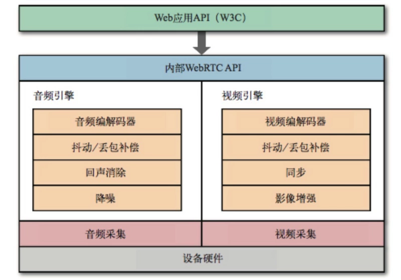
At the bottom, the browser uses the audio and video engine to process the captured raw audio and video streams. In addition to picture and sound enhancement, the browser also ensures that the audio and video are synchronized.
Since audio and video are used for transmission, the sender also adjusts the output bit rate to accommodate changing bandwidth and network latency between clients.
For the receiver, the audio and video streams must be decoded in real time to accommodate network jitter and latency.It works as follows:
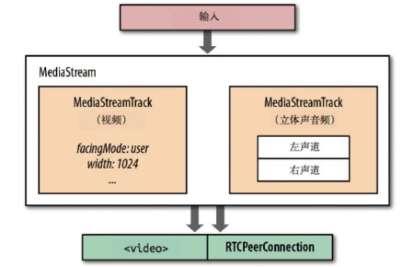
If you set both audio and video to true in the constraint, then audio and video tracks will be carried in the stream, and each Track will be synchronized in time.
The output of a stream can be sent to one or more destinations: local audio or video elements, a JavaScript proxy for post-processing, or the remote other end.As shown in the following figure:
RTCPeerConnection
After you get the audio and video streams, the next step is to send them out.However, unlike client-server mode, this is a transport between client-client s, so NAT penetration must be addressed at the protocol level, otherwise the transport cannot be discussed.
In addition, since WebRTC is primarily used to solve real-time communication problems, reliability is not important, so WebRTC uses UDP as the transport layer protocol: low latency and timeliness are key.
Before going into more detail, let's think about whether it's OK to just turn on audio and video and send a UDP package?
Of course, it's not that simple. In addition to solving the NAT penetration problem we mentioned above, we need to negotiate parameters for each stream, encrypt user data, and implement congestion and traffic control.
Let's look at a layered protocol diagram for WebRTC:
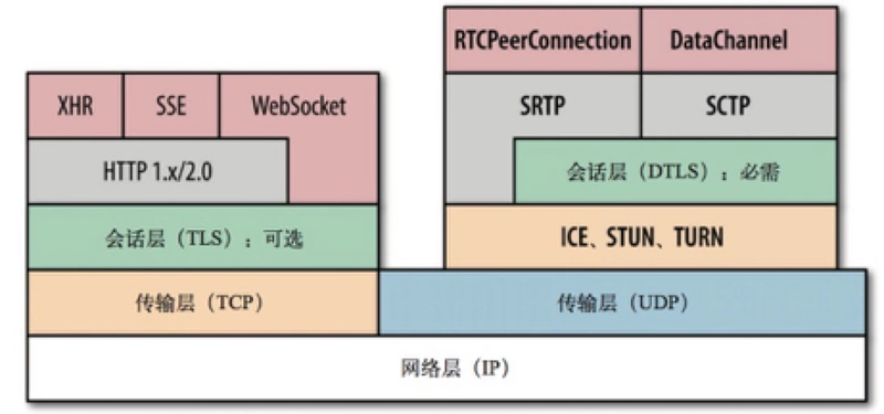
ICE, STUN, and TURN are required to establish and maintain end-to-end connections through UDP; SDP is a data format for negotiating parameters on end-to-end connections; DTLS is used to secure data transmission; SCTP and SRTP are application-layer protocols that provide multiplexing, congestion, and flow control of different flows over UDP; andPartially reliable delivery and other services.
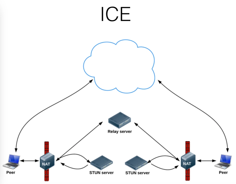
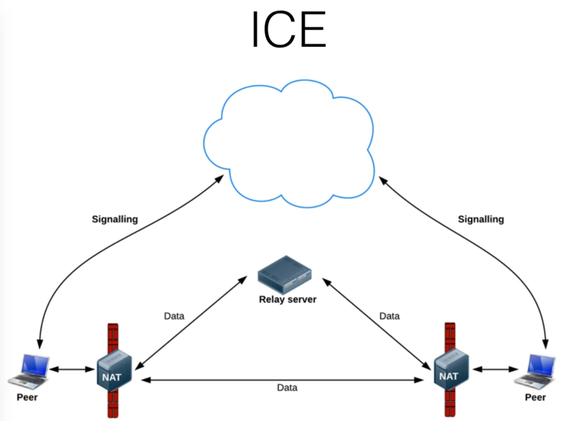
ICE (Interactive Connectivity Establishment): Since there are multiple firewalls and NAT devices blocking the ends, we need a mechanism to collect IP for public lines between the ends, and ICE is a good helper in this.
- ICE Proxy Queries Local IP Address from Operating System
- If a STUNserver is configured, the ICE proxy queries the external STUNserver for public IP and ports on the local end
- If a TURN server is configured, ICE will use the TURN server as a candidate, and when the end-to-end connection fails, the data will be forwarded through the specified intermediate device.
WebRTC uses SDP (Session Description Protocol) to describe end-to-end connection parameters.
SDP does not contain any information about the media itself and is only used to describe the "session state" as a series of connection properties: the type of media to be exchanged (audio, video, and application data), the network transport protocol, the codec used and its settings, bandwidth, and other metadata.
DTLS extends the TLS protocol by explicitly adding offset fields and serial numbers to each handshake record, which meets the criteria for orderly delivery and allows large records to be segmented into groups and assembled on the other end.
DTLS handshake records are transmitted strictly in the order specified by the TLS protocol, and errors occur if the order is not correct.Finally, DTLS has to deal with packet dropouts: both ends are timers, and if no response is received at the scheduled time, the handshake record is retransmitted.
To ensure the process is complete, both sides need to generate their own signed certificates, and then follow the regular TLS handshake protocol.However, such a certificate cannot be used to authenticate because there is no trust chain to authenticate.Therefore, if necessary,
Applications must participate in authentication on each end themselves:
- Applications can authenticate users by logging in
- Each end can also specify its own "identity authority" when generating SDP proposals/responses, and when the peer receives an SDP message, it can contact the specified identity authority to verify the received certificate.
SRTP defines a standard grouping format for delivering audio and video over an IP network.SRTP itself does not provide any assurance mechanism for the timeliness, reliability or data recovery of transmitted data.
It is only responsible for encapsulating digitized audio sampling and video frames with some metadata to assist the recipient in processing these streams.
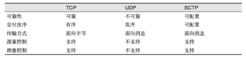
SCTP is a transport layer protocol that runs directly over the IP protocol, similar to TCP and UDP.However, here in WebRTC, SCTP runs in a secure DTLS channel that runs on top of UDP.
Since WebRTC supports the transfer of arbitrary application data from end to end through the DataChannel API, DataChannel relies on SCTP.
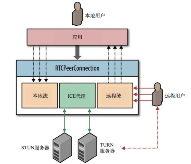
That's all, and finally to our protagonist, RTCPeerConnection, the RTCPeerConnection interface is responsible for maintaining the full lifecycle of each end-to-end connection:
- RTCPeerConnection manages complete ICE workflows across NAT
- RTCPeerConnection Sends Automatic (STUN) Persistence Signal
- RTCPeerConnection tracks local streams
- RTCPeerConnection tracks remote streams
- RTCPeerConnection triggers automated flow negotiation on demand
- RTCPeerConnection provides the necessary API s to generate connection proposals, receive responses, allow us to query the current status of connections, etc.
Let's take a look at the sample code:
var signalingChannel = new SignalingChannel();
var pc = null;
var ice = {
    "iceServers": [
        { "url": "stun:stun.l.google.com:19302" }, //Use the google public test server
        { "url": "turn:user@turnserver.com", "credential": "pass" } // If there is a turn server, you can configure it here
    ]
};
signalingChannel.onmessage = function (msg) {
    if (msg.offer) { // Monitor and process remote proposals delivered through the outgoing channel
        pc = new RTCPeerConnection(ice);
        pc.setRemoteDescription(msg.offer);
        navigator.getUserMedia({ "audio": true, "video": true }, gotStream, logError);
    } else if (msg.candidate) { // Register remote ICE candidates to start connection checking
        pc.addIceCandidate(msg.candidate);
    }
}
function gotStream(evt) {
    pc.addstream(evt.stream);
    var local_video = document.getElementById('local_video');
    local_video.src = window.URL.createObjectURL(evt.stream);
    pc.createAnswer(function (answer) { // Generate SDP replies describing end connections and send them to the opposite end
        pc.setLocalDescription(answer);
        signalingChannel.send(answer.sdp);
    });
}
pc.onicecandidate = function (evt) {
    if (evt.candidate) {
        signalingChannel.send(evt.candidate);
    }
}
pc.onaddstream = function (evt) {
    var remote_video = document.getElementById('remote_video');
    remote_video.src = window.URL.createObjectURL(evt.stream);
}
function logError() { ... }
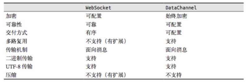
DataChannel
DataChannel supports end-to-end data exchange for any application, just like a WebSocket, but end-to-end.
After an RTCPeerConnection connection is established, one or more channels can be opened at both ends to exchange text or binary data.
An example demo is as follows:
var ice = {
    'iceServers': [
        {'url': 'stun:stun.l.google.com:19302'},   // google public test server
        // {"url": "turn:user@turnservera.com", "credential": "pass"}
    ]
};

// var signalingChannel =  new SignalingChannel();

var pc = new RTCPeerConnection(ice);

navigator.getUserMedia({'audio': true}, gotStream, logError);

function gotStream(stram) {
    pc.addStream(stram);

    pc.createOffer().then(function(offer){
        pc.setLocalDescription(offer);
    });
}

pc.onicecandidate = function(evt) {
    // console.log(evt);
    if(evt.target.iceGatheringState == 'complete') {
        pc.createOffer().then(function(offer){
            // console.log(offer.sdp);
            // signalingChannel.send(sdp);
        })
    }
}

function handleChannel(chan) {
    console.log(chan);
    chan.onerror = function(err) {}
    chan.onclose = function() {}
    chan.onopen = function(evt) {
        console.log('established');
        chan.send('DataChannel connection established.');
    }

    chan.onmessage = function(msg){
        // do something
    }
}


// Initialize the new DataChannel with appropriate delivery semantics
var dc = pc.createDataChannel('namedChannel', {reliable: false});

handleChannel(dc);
pc.onDataChannel = handleChannel;


function logError(){
    console.log('error');
}
Original: https://segmentfault.com/a/1190000011403597
For individual learning and communication only