cubemx configuration STM32 (III)__ Input and output of GPIO
1. Establish the project and carry out core configuration
According to the article 2. Use cubemx to configure STM32 (II)__ Core configuration Configure as follows:
CubeMX new project
CubeMX graphic configuration debug clock signal
CubeMX graphic configuration clock tree
CubeMX graphic configuration debugging interface
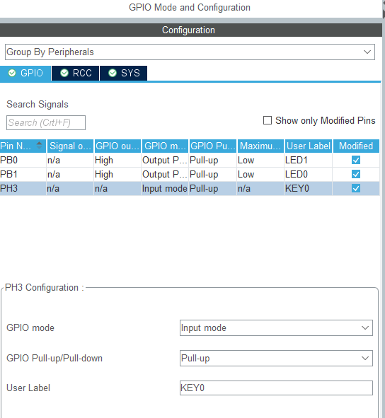
Check configuration:
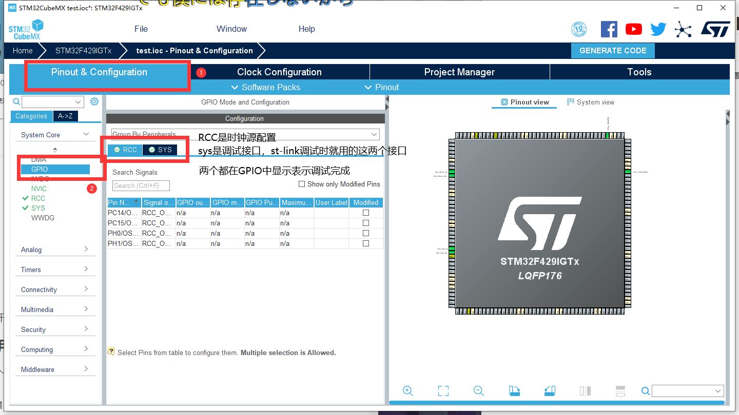
Configuration details
1. Configure and select I / O
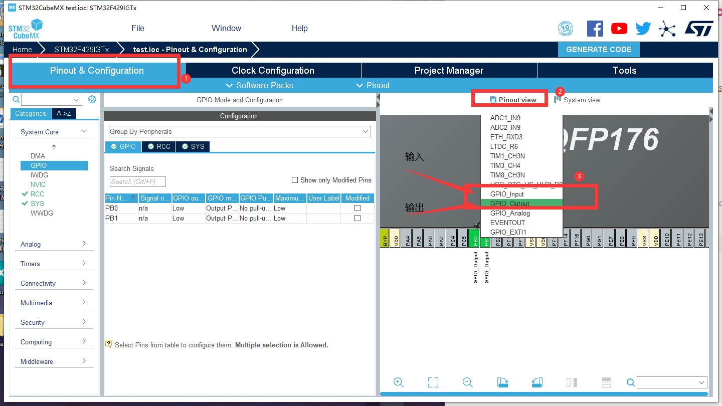
For example, LED should be configured with output and key should be configured with input
2. Configuration details when configured as output (at this time, I configure this chip PB1 as output, and other pins of other chips can be used. Please refer to the schematic diagram of the development board in your hand)

(1).GPIO output level (pin initial level setting)
- The High output is initialized to a High level
- The Low output is initialized to a Low level
(2) . GPIO mode (GPIO output mode) - Output Push pull output has strong high and low levels, which can supply power to IO equipment
- The Output Open Drain output mode is strong low level. Only low level can supply power to IO equipment, but high level can only be output as a signal
(3) . GPIO pull up / pull down
- No pull up and no pull down
- Pull up internal pull-up resistance
- Pull down internal resistance
(4) . maximum output speed (pin speed setting)
- Low low speed
- Medium medium speed
- High speed
- Very High
(5) . user label
- Set the name of the pin, such as LED0
2. Configuration details when configured as input (at this time, I configure PH3 of this chip as input, and other pins of other chips can be used. Please refer to the schematic diagram of the development board in hand)
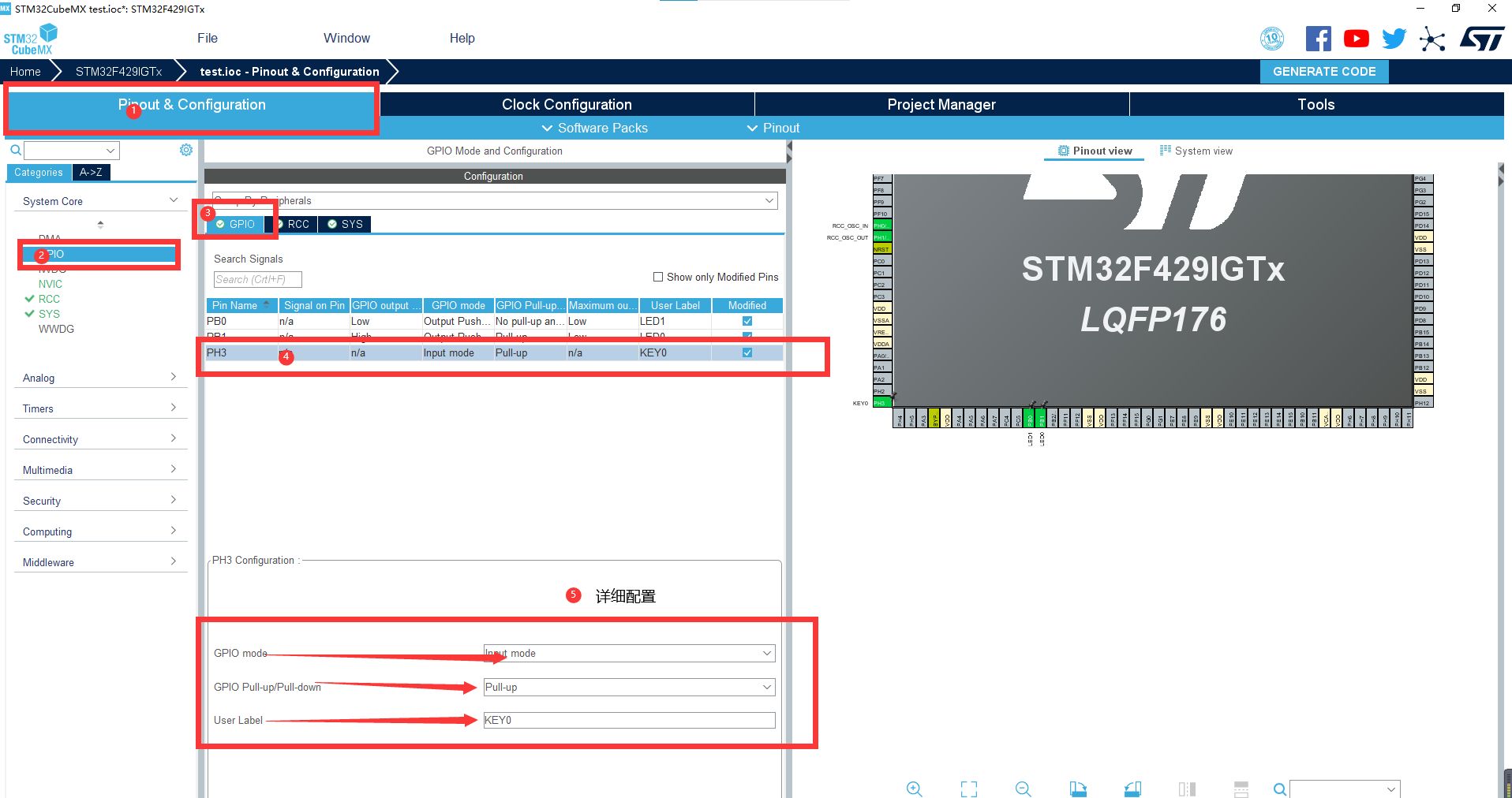
(1) . GPIO mode (GPIO input mode)
- Input mode
(2) . GPIO pull up / pull down
- No pull up and no pull down
- Pull up internal pull-up resistance
- Pull down internal resistance
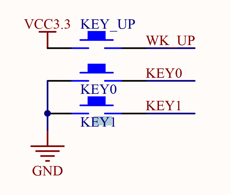
As shown in the figure below, one end of KEY0 and KEY1 is grounded. If the key is pressed, it is low level. We should make the key high level when the key is not pressed, so we should pull it up internally. After pulling up, the signal is high level when the key is not pressed
Similarly, key_ The up end is connected to VCC. If the key is pressed, it is high level. We should make the key low level when the key is not pressed, so we should pull it down internally. After the pull-down, the signal is low level when the key is not pressed
(3) . user label
- Set the name of the pin, such as KEY0
2. Example: configure PB1 PB0 PH3 and generate code


After selecting the project to generate the software, click "GENERATE CODE" in the upper right corner
See the following article for relevant small project code examples
3. Explanation and application of key codes
1. Generate initialization function code (manually added comments)
static void MX_GPIO_Init(void)
{
  GPIO_InitTypeDef GPIO_InitStruct = {0};

  /* GPIO Ports Clock Enable */
  __HAL_RCC_GPIOC_CLK_ENABLE(); //Enable the GPIOC clock, and the external clock input uses pc14 and PC15
  __HAL_RCC_GPIOH_CLK_ENABLE(); //Enable the GPIOH clock because the key uses PH3 and the external clock input uses pH0 and Ph1
  __HAL_RCC_GPIOB_CLK_ENABLE(); //Enable the GPIOB clock because the LED uses PB0 PB1
  __HAL_RCC_GPIOA_CLK_ENABLE(); //Enable the GPIOA clock because the debug download interface uses pa13 and PA14

  /*Configure GPIO pin Output Level */
 HAL_GPIO_WritePin(GPIOB, LED1_Pin|LED0_Pin, GPIO_PIN_SET);//LED1 and LED0 have the same configuration and can be configured at the same time
															//Configure as initial level high level
  /*Configure GPIO pin : KEY0_Pin */  //GPIO initialization configuration for keys
  GPIO_InitStruct.Pin = KEY0_Pin;//There is #define key0 in main.h_ Pin GPIO_ PIN_ 3 corresponding to PH3
  GPIO_InitStruct.Mode = GPIO_MODE_INPUT;//The mode is input mode
  GPIO_InitStruct.Pull = GPIO_PULLUP;//Internal resistance pull-up
  HAL_GPIO_Init(KEY0_GPIO_Port, &GPIO_InitStruct);//Initialize according to the above

  /*Configure GPIO pins : LED1_Pin LED0_Pin */
    //LED1 and LED0 have the same configuration and can be configured at the same time

  GPIO_InitStruct.Pin = LED1_Pin|LED0_Pin;//Two LED s are configured here, that is, the output of GPIO
    //There is #define LED0 in main.h_ Pin GPIO_ PIN_ 1, #define LED1_Pin GPIO_PIN_0 corresponds to 1 and 0 of PB1 PB0
  GPIO_InitStruct.Mode = GPIO_MODE_OUTPUT_PP;//The mode is push-pull output
  GPIO_InitStruct.Pull = GPIO_PULLUP;//Internal resistance pull-up
  GPIO_InitStruct.Speed = GPIO_SPEED_FREQ_LOW;//The output speed is low
  HAL_GPIO_Init(GPIOB, &GPIO_InitStruct);//Initialize according to the above

}
2. Application of correlation function