The operation applied to the geometric description of an object and changing its position, direction or size is called geometric transformation.
Geometric transformations are sometimes referred to as modeling transformations. Modeling transformation is generally used to construct scenes or give hierarchical descriptions of complex objects composed of multiple parts. On the other hand, geometric transformation can be used to describe how objects in the animation sequence can move in the scene or simply observe them from another angle.
Basic two-dimensional geometric transformation
Translation, rotation and scaling are geometric transformation functions included in all graphics packages. Other transformation functions that may be included in the graphics package are reflection and stagger operations.
2D translation
By adding the displacement to the coordinates of a point to generate a new coordinate position, one translation can be realized.
Add the translation distances tx and ty to the original coordinates (x, y) to obtain a new coordinate position It can realize the translation of a two-dimensional position,

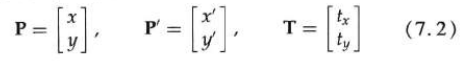
A set of translation distances (tx, ty) is called a translation vector or a displacement vector.
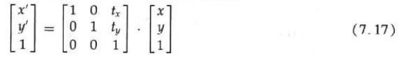
The two-dimensional translation equation can be expressed in matrix form:

The following program implements the translation operation:
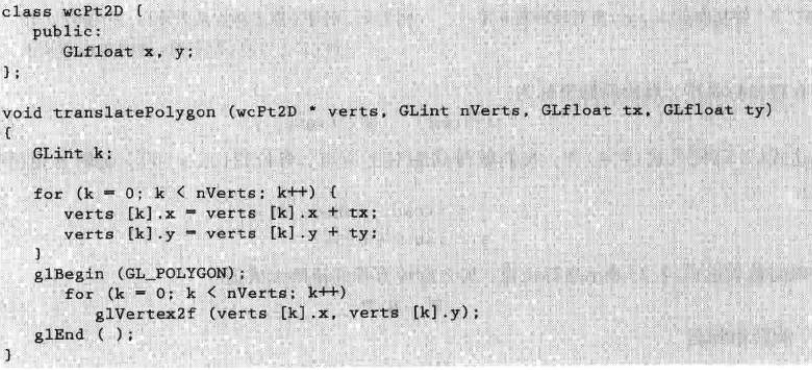
You can use the same method to translate other objects. In order to change the position of the circle or ellipse, you can translate the central coordinates and redraw the figure at the new central position. For a spline curve, the points on the curve path are defined by translation, and then the translated coordinate positions are used to reconstruct the curve.
2D rotation
You can perform a rotation transformation by specifying an axis of rotation and an angle of rotation. After all vertices of an object are rotated around the specified rotation axis at the specified angle, all points of the object are rotated to the new position.
The two-dimensional rotation of the object is achieved by repositioning the object along the circular path on the xy plane. At this point, we rotate the object about an axis of rotation perpendicular to the xy plane (parallel to the z axis). The parameters of two-dimensional rotation are rotation angle and position called rotation point, around which the object rotates.
Determine the transformation equation for the rotation of the point position P when the reference point is the coordinate origin.
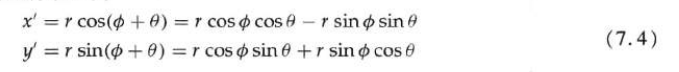
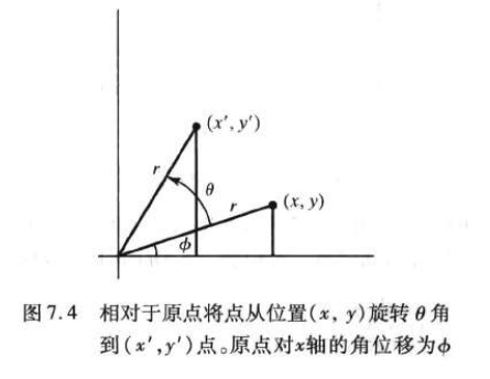
The original coordinates of the point are:

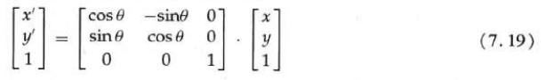
By substituting into the above formula, the transformation equation of rotating the point of position (x, y) by a specified angle relative to the origin is obtained:
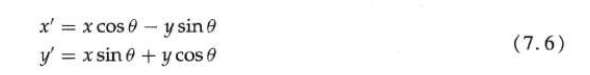
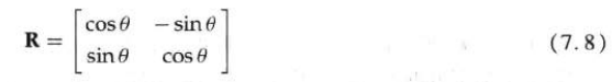
The matrix form of the rotation equation is:

The rotation matrix is:
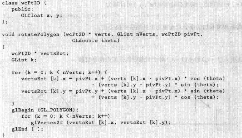
Polygon rotation is to rotate each vertex by a specified rotation angle, and use new vertices to generate polygons to realize rotation. The rotation of the curve is accomplished by repositioning the defined points and redrawing the curve.
In the following procedure, a polygon rotates around a reference point in the specified world coordinate system.
2D zoom
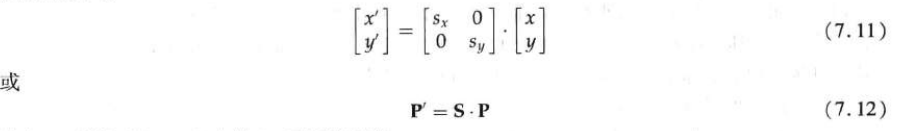
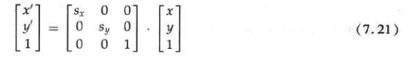
To change the size of an object, you can use scale transformation. A simple two-dimensional scaling operation can be obtained by multiplying the scaling coefficients sx and sy by the object coordinate position (x, y):

Matrix form of basic 2D scaling formula:
When sx and sy are assigned the same value, the relative scale of the object will be kept consistent. When sx and sy values are not equal, the difference scaling common in design applications will occur.
You can select a point that does not change its position after scaling, called a fixed point, to control the position of the scaled object. The coordinates of the fixed point (xf, yf) can select the midpoint of the object or any other spatial location. In this way, the polygon is scaled relative to the fixed point by scaling the distance from each vertex to the fixed point. For vertices with coordinates (x, y), the scaled coordinates can be calculated as:
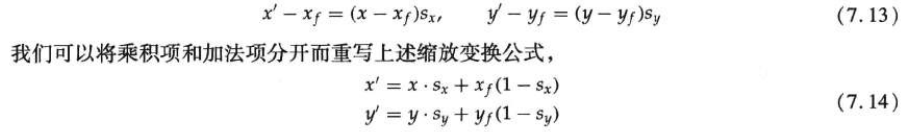
Polygon scaling can be achieved by applying the transformation equation to each vertex, and then regenerating the polygon from the transformed vertices.
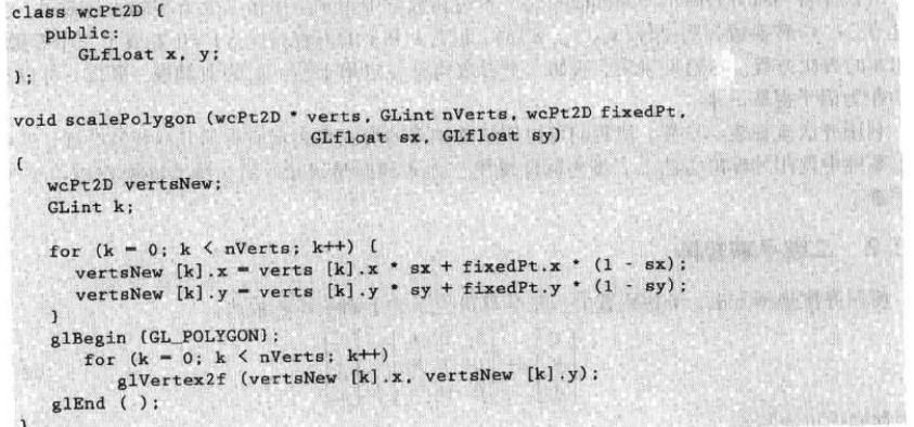
The following program gives an example of calculating the scaling of a polygon.
Matrix representation and homogeneous coordinates
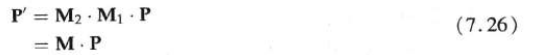
Each basic transformation (translation, rotation, and scaling) can be represented as a normal matrix

In order to use this formula to generate the transformation order of first scaling, then rotating and then translating, the transformed coordinates must be calculated step by step. The more effective method is to combine the transformations to obtain the final coordinate position directly from the initial coordinates, which eliminates the calculation of intermediate coordinate values.
Homogeneous coordinates
If the 2 x 2 matrix expression is extended to 3 x 3 matrix, the multiplication and translation of two-dimensional set transformation can be combined into a single matrix representation. The standard implementation technology is to expand the two-dimensional coordinate position representation (x, y) to the three-dimensional representation (xh, yh, H), which is called homogeneous coordinate. Here, the homogeneous parameter h is a non-zero value. Therefore:

Using homogeneous coordinates to represent the position, we can express all geometric transformation formulas in the form of matrix multiplication, which is a standard method used in graphics system.
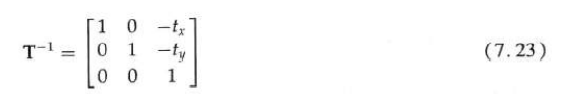
Two dimensional translation matrix

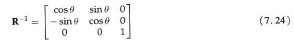
Two dimensional rotation matrix

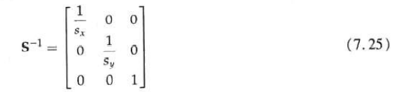
Two dimensional scaling matrix

inverse transformation
Two dimensional compound transformation
Since many positions in the scene are transformed in the same order, it will be an efficient method to multiply all transformation matrices to form a composite matrix.
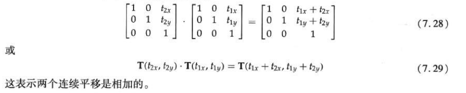
Composite 2D translation
Composite 2D rotation

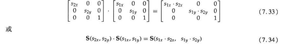
Composite 2D scaling
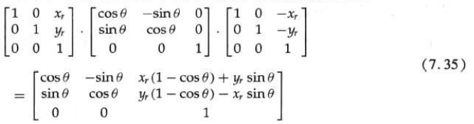
General 2D datum rotation
When the graphics software package only provides the rotation function around the coordinate origin, the rotation around any selected reference point (xr, yr) can be realized by completing the following translation rotation translation operation sequence.
1. Translate the object to move the reference point position to the coordinate origin;
2. Rotate around the coordinate origin;
3. Translate the object so that the reference point returns to its original position.

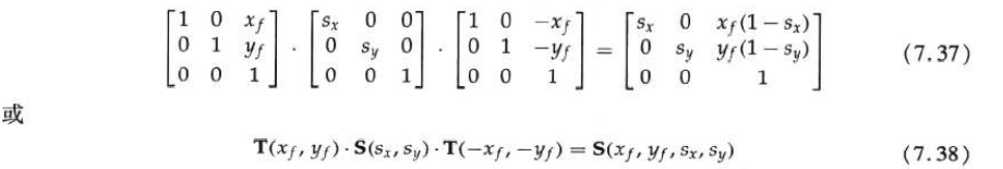
Universal 2D datum scaling
For the transformation sequence scaled at any selected reference position (xf, yf):
1. Translate the object so that the fixed point coincides with the coordinate origin;
2. Scale the coordinate origin;
3. Use the reverse translation in step 1 to return the object to its original position.
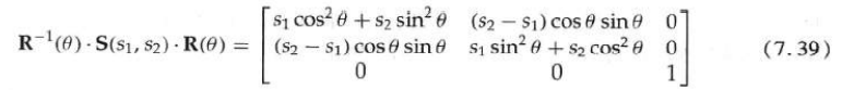
General 2D directional scaling
In order to complete this scaling without changing the object direction, first complete the rotation operation so that the directions of s1 and s2 coincide with the x and y axes respectively. Then, the scaling transformation s (s1, s2) is applied, and then the reverse rotation is performed to return to its original position. The composite matrix obtained by the product of these three transformations is:
Matrix merging characteristics
Matrix multiplication conforms to the law of association. The transformation product is generally not exchangeable. For the special case that each type of transformation sequence is the same, the multiple multiplication of transformation matrix is commutative.
General two-dimensional compound transformation and computational efficiency
A general 2D transform representing a combination of translation, rotation, and scaling can be represented as
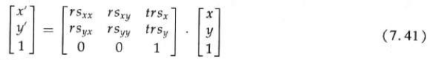
Once a single matrix is connected to calculate the element values of the composite matrix, this is the maximum number of calculations required for any transformation sequence.
The effective implementation of transformation operation is to form transformation matrix, merge all transformation sequences, and then calculate transformation coordinates.
Because the rotation calculation needs triangular evaluation and multiple multiplication for each transformation point, the calculation efficiency in the rotation transformation has become a very important problem. In animation and other applications including many repeated transformations and small rotation angles, approximation and cyclic calculation can be used to reduce the amount of calculation in the composite transformation equation. For a sufficiently small angle (less than 10 °), cos is approximately 1 and sin is approximately the radian value of the angle.
Among them, as long as the rotation angle does not change, sin only needs one value for all steps. After many steps, the accumulated error will also become large. The object position must be reset when the error accumulation becomes too large.
2D rigid body transformation
If a transformation matrix contains only translation and rotation parameters, it is a rigid body transformation matrix. The general form of two-dimensional rigid body transformation matrix is:
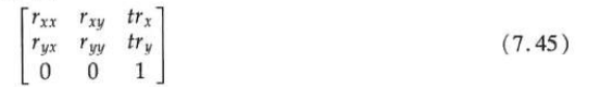
The rigid body change of coordinate position sometimes becomes the rigid body motion transformation. After transformation, all angles and distances between coordinate positions do not change. In addition, the matrix (7.45) has the characteristic that the upper left corner 2x2 is an orthogonal matrix.


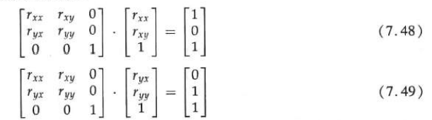
Therefore, if these unit vectors are transformed by rotating the submatrix, (rxx, rxy) is converted into unit vectors along the x axis, and (ryx, ryy) is converted into unit vectors along the y axis of the coordinate system:
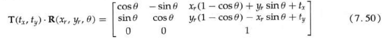
As an example, the following rigid body transformation first rotates the object by an angle with respect to the reference point (xr, yr), and then translates:
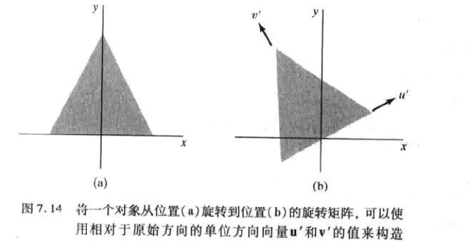
Construct two-dimensional rotation matrix
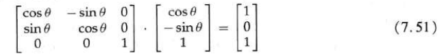
The orthogonality of the rotation matrix can be used to construct the matrix when the rotation angle required to place the object in this position is not known until the last direction of the object.
The direction information can be determined by aligning with an object in the scene or by a selected position in the scene.
Programming example of two-dimensional composite matrix
The triangle first scales its center position, then rotates around its center, and finally translates.
#include <GL/glut.h>
#include <stdlib.h>
#include <math.h>

GLsizei winWidth = 600, winHeight = 600;

GLfloat xwcMin = 0.0, xwcMax = 225.0;
GLfloat ywcMin = 0.0, ywcMax = 225.0;

class wcPt2D
{
public:
	GLfloat x, y;
};

typedef GLfloat Matrix3x3[3][3];

Matrix3x3 matComposite;

const GLdouble pi = 3.14159;

void Init()
{
	glClearColor(1.0, 1.0, 1.0, 0.0);
}

void Matrix3x3SetIdentity(Matrix3x3 matIdent3x3)
{
	GLint row, col;

	for (row  = 0;  row < 3; row++)
	{
		for (col = 0; col < 3; col++)
		{
			matIdent3x3[row][col] = (row == col);
		}
	}
}

void Matrix3x3PreMultiply(Matrix3x3 m1, Matrix3x3 m2)
{
	GLint row, col;
	Matrix3x3 matTemp;

	for (row = 0; row < 3; row++)
	{
		for (col = 0; col < 3; col++)
		{
			matTemp[row][col] =
				m1[row][0]* m2[0][col] +
				m1[row][1]* m2[1][col]+
				m1[row][2]* m2[2][col];
		}
	}

	for (row = 0; row < 3; row++)
	{
		for (col = 0; col < 3; col++)
		{
			m2[row][col] = matTemp[row][col];
		}
	}
}

void Translate2D(GLfloat tx, GLfloat ty)
{
	Matrix3x3 matTransl;

	Matrix3x3SetIdentity(matTransl);

	matTransl[0][2] = tx;
	matTransl[1][2] = ty;

	Matrix3x3PreMultiply(matTransl, matComposite);
}

void Rotate2D(wcPt2D pivotPt, GLfloat theta)
{
	Matrix3x3 matRot;

	Matrix3x3SetIdentity(matRot);

	matRot[0][0] = cos(theta);
	matRot[0][1] = -sin(theta);
	matRot[0][2] = pivotPt.x * (1-cos(theta)) +
		pivotPt.y * sin(theta);

	matRot[1][0] = sin(theta);
	matRot[1][1] = cos(theta);
	matRot[1][2] = pivotPt.y * (1 - cos(theta)) -
		pivotPt.x * sin(theta);

	Matrix3x3PreMultiply(matRot, matComposite);
}

void Scale2D(GLfloat sx, GLfloat sy, wcPt2D fixedPt)
{
	Matrix3x3 matScale;

	Matrix3x3SetIdentity(matScale);

	matScale[0][0] = sx;
	matScale[0][2] = (1 - sx) * fixedPt.x;

	matScale[1][1] = sy;
	matScale[1][2] = (1 - sy) * fixedPt.y;

	Matrix3x3PreMultiply(matScale, matComposite);
}

void TransformVerts2D(GLint nVerts, wcPt2D * verts)
{
	GLint k;
	GLfloat temp;

	for (k = 0; k < nVerts; k++)
	{
		temp = matComposite[0][0] * verts[k].x +
			matComposite[0][1] * verts[k].y +
			matComposite[0][2];

		verts[k].y = matComposite[1][0] * verts[k].x +
			matComposite[1][1] * verts[k].y +
			matComposite[1][2];
		verts[k].x = temp;
	}
}

void Trangle(wcPt2D * verts)
{
	GLint k;

	glBegin(GL_TRIANGLES);
	for (k = 0; k < 3; k++)
	{
		glVertex2f(verts[k].x, verts[k].y);
	}
	glEnd();
}

void WinReshapFcn(GLint newWidth, GLint newHeight)
{
	glMatrixMode(GL_PROJECTION);
	glLoadIdentity();
	gluOrtho2D(xwcMin, xwcMax, ywcMin, ywcMax);

	glClear(GL_COLOR_BUFFER_BIT);
}

void DisplayFcn()
{
	GLint nVerts = 3;
	wcPt2D verts[3] = { {50,25},{150,25 },{100,100} };

	wcPt2D centroidPt;

	GLint k, xSum = 0, ySum = 0;

	for (size_t k = 0; k < nVerts; k++)
	{
		xSum += verts[k].x;
		ySum += verts[k].y;
	}

	centroidPt.x = GLfloat(xSum) / GLfloat(nVerts);
	centroidPt.y = GLfloat(ySum) / GLfloat(nVerts);

	wcPt2D pivPt, fixedPt;
	pivPt = centroidPt;
	fixedPt = centroidPt;

	GLfloat tx = 0, ty = 100;
	GLfloat sx = 0.5, sy = 0.5;
	GLdouble theta = pi / 2;

	glClear(GL_COLOR_BUFFER_BIT);

	glColor3f(0, 0, 1);
	Trangle(verts);

	Matrix3x3SetIdentity(matComposite);

	Scale2D(sx, sy, fixedPt);
	Rotate2D(pivPt, theta);
	Translate2D(tx, ty);

	TransformVerts2D(nVerts, verts);

	glColor3f(1, 0, 0);
	Trangle(verts);

	glFlush();
}

int main(int argc, char* argv[])
{
	glutInit(&argc, argv);
	glutInitDisplayMode(GLUT_SINGLE | GLUT_RGB);
	glutInitWindowPosition(50, 50);
	glutInitWindowSize(winWidth, winHeight);
	glutCreateWindow("Geometric Transformation Sequence");

	Init();
	glutDisplayFunc(DisplayFcn);
	glutReshapeFunc(WinReshapFcn);

	glutMainLoop();
	return 0;
}
Other 2D transformations
reflex
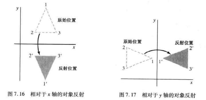
The transformation that produces a mirror image of an object is called reflection.
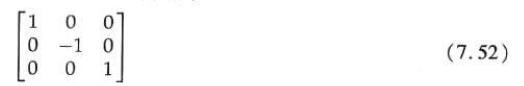
The reflection of y = 0 (x-axis) can be completed by the following transformation matrix:
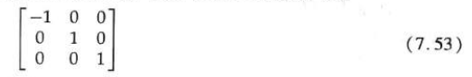
For the reflection with x = 0 (y axis), flip the X coordinate and keep the y coordinate unchanged. The matrix of this transformation is:
The reflection transformation of any line can be completed by a series of translation, rotation and axis reflection matrix combination.
Staggered cutting
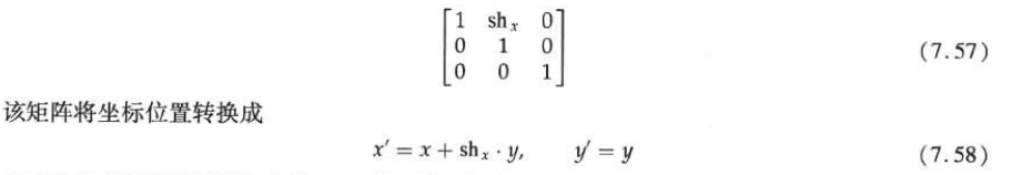
Staggering is a transformation that changes the shape of an object. The object after staggering seems to be composed of internal interlayers that have slid each other. Two commonly used staggered transformations are the staggered transformation of moving x coordinate value and the staggered transformation of moving y coordinate value.
The x-direction offset with respect to the x-axis is generated by the following transformation matrix:
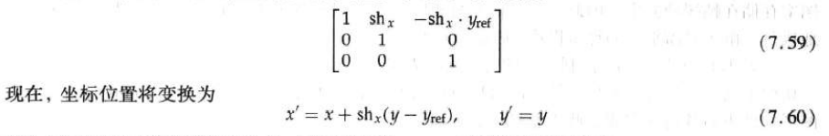
The following matrix can be used to generate x-direction tangents relative to other reference lines:
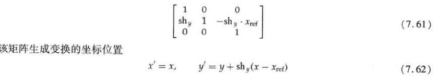
The following transformation matrix is used to generate the y-direction tangent relative to the line x = x ref:
The staggered cut operation can be expressed as a sequence of basic transformations.
Grating method of geometric transformation
The raster system stores the image information as a color pattern in the frame buffer. Therefore, some simple transformations can be performed quickly by manipulating a rectangular array of stored pixel values. Pixel transformation is particularly effective because only few arithmetic operations are required.
The raster function that controls the rectangular pixel array is usually called raster operation. The process of moving a pixel from one position to another also becomes the block movement of pixel values.
The two-dimensional translation completed as the block movement of the raster cache area is realized by copying all bits displayed in the rectangular area to another part of the raster as a block, and deleting the original object by filling the rectangular area of the block with background brightness.
In the general array rotation, each target region is mapped to the rotated grid, and its overlap value with the rotated pixel region is calculated. The brightness of the target pixel is calculated by averaging the brightness of the covered source pixel and weighting the percentage of area overlap. Or an approximate method such as anti aliasing is used to determine the color of the target pixel.
The raster scaling of the pixel block is realized in a similar way. The pixel area in the original block is scaled with the specified sx and sy values, and the scaled rectangle is mapped to a group of target pixels, and then the brightness of each target pixel is set according to its overlapping area with the scaled pixel area.
The reflection of raster objects can be completed by reversing the transformation of rows or columns in pixel blocks, combined with translation. Shifting pixel positions along rows or columns can achieve staggering.
OpenGL raster transform
The translation of the rectangular array of pixel color values from one cache to another can be completed as the following OpenGL copy operation:

This translation can be used as any refresh cache or between different caches. The source cache of the glCopyPixels function is selected by the glReadBuffer subroutine, while the target cache is selected by the glDrawBuffer subroutine.
By first storing the block in an array, then rearranging the elements of the array and putting them back into the refresh cache, the rotation of 90 ° multiples of pixel blocks can be realized. An RGB color block in the cache can be stored in an array with the following functions:

If the color table index is stored at the pixel location, GL is displayed_ COLOR_ Index replaces GL_RGB. Use the following statement to put the rotated array back into the cache:

Use glReadBuffer to select the source cache containing the original pixel value block, and glDrawBuffer to specify the target cache.
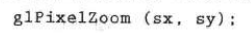
For raster operations, use the following functions to set the scaling factor:
Transformation between two-dimensional coordinate systems
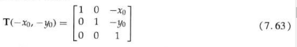
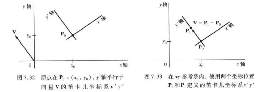
In order to convert the object description from xy coordinates to x 'y' coordinates, a transformation must be established to superimpose the x 'y' axis on the xy axis, which needs to be carried out in two steps:
1. Translate the coordinate origin (x0, y0) of X 'y' system to the origin (0, 0) of xy system;
2. Rotate the x 'axis onto the x axis.
The translation of the coordinate origin can be represented by the following matrix operations:
The rotation matrix is:
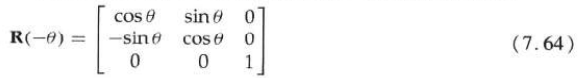
Combine the two matrices to obtain a composite matrix:

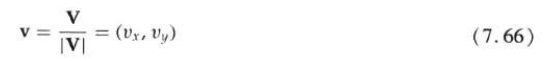
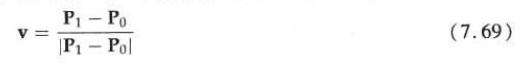
Another way is to specify a vector V that indicates the direction of the positive y 'axis. Specify vector V as a point in the xy reference system relative to the origin of the xy coordinate system. Then, the unit vector in the Y 'direction can be calculated as:
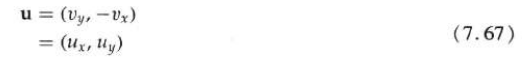
By rotating v clockwise by 90 °, the unit vector u along the x 'axis can be obtained:
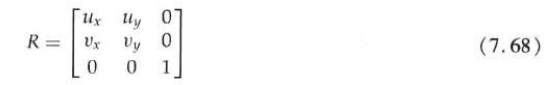
The elements of any rotation matrix can be represented as elements of a set of orthogonal unit vectors. Therefore, the matrix that rotates the x 'y' system to coincide with the xy system can be written as:
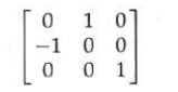
For example, if V = (- 1, 0), the rotation transformation matrix is:
In interactive applications, it is more convenient to select the orientation of V relative to position P0 than to specify its direction relative to the origin of xy coordinate. At this time, the component of V is calculated as:
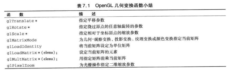
OpenGL 2D geometric transformation function
The two-dimensional transformation can be realized by selecting the Z value that does not change the third dimension (z) in OpenGL. To complete a translation, reference the translation subroutine and set the three-dimensional translation vector. In the rotation function, you need to specify the angle and direction of the rotation axis passing through the origin of the coordinate system. The scaling function is used to set three coordinate scaling coefficients relative to the origin of the coordinate system.
Basic OpenGL geometric transformation


It must be noted that OpenGL uses composite matrices internally to support transformations. This results in transformations that can be accumulated, that is, if you specify a translation and then a rotation, the object described by the position will obtain two transformations. If you do not want to do so, you must remove the effect of the previous transformation.
OpenGL matrix operation
Use the subroutine glMatrixMode to set the projection mode, that is, to specify the matrix to be used for projection transformation. The same subroutine can be used to set the geometric transformation matrix. However, at this time, the matrix is regarded as a modeling observation matrix, which is used to store and combine geometric transformations, as well as geometric transformations and transformations of observation coordinate system. The modeling observation mode is specified with the following statement:

This statement specifies a 4x4 modeling observation matrix as the current matrix. It must be used to modify the modeling observation matrix before geometric transformation.
This function can also set two other modes: texture mode and color mode. Texture mode is used to map the texture pattern of the surface, while color mode is used to convert from one color model to another.
Use the following functions to set the current matrix as the identity matrix:
You can merge the specified matrix with the current matrix:


In this sequence, the first transformation applied is the last one specified in the program.
It is equally important that OpenGL stores matrices in a finite order of columns.
OpenGL actually provides a stack for each of the four modes selected using the glMatrixMode subroutine.
Summary
The basic geometric transformations are translation, rotation, and scaling. Translation moves an object from one location along a straight path to another. Rotation moves an object from one position to another along a circumferential path around a specified axis of rotation. Scaling transforms change the size of objects relative to fixed points.
The two-dimensional transformation can be represented by 3x3 matrix operation, so that a series of transformations can be combined into a composite matrix.
For a two-dimensional system, the transformation between two-dimensional coordinate systems is realized by a set of translation rotation transformations that make the two systems consistent.
The OpenGL basic library contains three functions for individual translation, rotation and scaling transformations of coordinate positions. Geometric transformations must be specified in reverse order.
There are several operations in OpenGL that can be used to complete raster transformation.
OpenGL geometric transformation function and matrix subroutine are as follows: