In previous blogs, we drew triangles, squares, circles and cubes. Today we will draw cones, cylinders and spheres. After these basic conventional geometric shapes can be drawn, the drawing of other common geometric shapes is basically no problem for us.
Drawing cones
From the previous blog, we should all know that the focus of object drawing in OpenGL ES2.0 is to decompose the surface of the object into triangles. After decomposition, the drawing will not be a problem. It is easy to think of a cone as a circle and a cone. The vertex of the cone is identical to the vertex of the circle except that the coordinates of the central point of the cone have a "height". The circle has been drawn in Android OpenGLES 2.0 (4) - square and circle, so the cone is actually a small case for us:
ArrayList<Float> pos=new ArrayList<>();
pos.add(0.0f);
pos.add(0.0f);
pos.add(height);        //Increase the height of the center of the circle relative to the edge to form a cone
float angDegSpan=360f/n;
for(float i=0;i<360+angDegSpan;i+=angDegSpan){
    pos.add((float) (radius*Math.sin(i*Math.PI/180f)));
    pos.add((float)(radius*Math.cos(i*Math.PI/180f)));
    pos.add(0.0f);
}
float[] d=new float[pos.size()];    //All vertices
for (int i=0;i<d.length;i++){
    d[i]=pos.get(i);
}
We draw a cone by drawing a circle, and then draw a circle at the bottom of the cone, so that we get a cone:
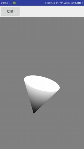
We can see from the figure that we are not drawing the same color. If we use the same color, it is difficult to see the stereoscopic effect of the cone. How does this color work? Let's look at its vertex shader (the chip shader is the same as before):
uniform mat4 vMatrix;
varying vec4 vColor;
attribute vec4 vPosition;

void main(){
    gl_Position=vMatrix*vPosition;
    if(vPosition.z!=0.0){
        vColor=vec4(0.0,0.0,0.0,1.0);
    }else{
        vColor=vec4(0.9,0.9,0.9,1.0);
    }
}
In the vertex shader, there is no incoming color, but the assignment is directly judged in the program. Of course, there are also vertex color and edge color that can be imported from outside. In the shader, we no longer simply assign values, but add process control. In the next blog, we will focus on the Shader Language GLSL, Android OpenGLES 2.0 (7) - the Shader Language GLSL.
Drawing a cylinder
The cylinder is similar to the cone. We can split the cylinder into two upper and lower surfaces and add a cylinder. We haven't drawn a cylinder before. How does it split into triangles? We can understand the cylinder like the idea of dismantling the circle. Think of Zheng Mitsubishi Column, Zheng Ba Ling Column, Zheng Bai Ling Column... The more diamonds there are, the smoother it will be and the closer it will be to the cylinder. Then each diamond (rectangle) will be broken into two triangles. The vertex of the disassembly is:
ArrayList<Float> pos=new ArrayList<>();
float angDegSpan=360f/n;
for(float i=0;i<360+angDegSpan;i+=angDegSpan){
    pos.add((float) (radius*Math.sin(i*Math.PI/180f)));
    pos.add((float)(radius*Math.cos(i*Math.PI/180f)));
    pos.add(height);
    pos.add((float) (radius*Math.sin(i*Math.PI/180f)));
    pos.add((float)(radius*Math.cos(i*Math.PI/180f)));
    pos.add(0.0f);
}
float[] d=new float[pos.size()];
for (int i=0;i<d.length;i++){
    d[i]=pos.get(i);
}
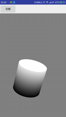
So we can draw a cylinder, just draw a circle at the top and a circle at the bottom, and we get a cylinder:
Drawing a sphere
Relative to conical cylinders, the disassembly of spheres is much more complicated. The common disassembly methods are to disassemble the spheres according to latitude and longitude and to disassemble the spheres according to regular polyhedron.
Method of dismantling regular polyhedron:
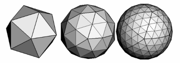
The method of longitude and latitude is dismantled (each block is regarded as a rectangle and then dismantled into a triangle). :
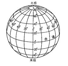
From the graph, we can also see that although polyhedron looks good, it is still easy to disassemble and calculate in the way of longitude and latitude, after all, the law is so obvious.
Coordinates of points on a sphere
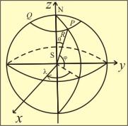
The coordinates of the points on the sphere need to be known whether they are split by latitude and longitude or by polyhedron. This is basic geometric knowledge. If the center of the sphere is the coordinate center and the radius of the sphere is R, then the coordinates of the points on the sphere are:
(R∗cos(ψ)∗sin(λ),R∗sin(ψ),R∗cos(ψ)∗cos(λ))
(R∗cos(ψ)∗sin(λ),R∗sin(ψ),R∗cos(ψ)∗cos(λ))
Among them, _is the angle between the line segment from the center to the point and the xz plane, and lambda is the angle between the projection of the line segment from the center to the point on the xz plane and the z axis. Graphical representation is as follows:
Disassembly vertex
The vertex array of the sphere is obtained by disassembling the sphere according to longitude and latitude.
ArrayList<Float> data=new ArrayList<>();
float r1,r2;
float h1,h2;
float sin,cos;
for(float i=-90;i<90+step;i+=step){
    r1 = (float)Math.cos(i * Math.PI / 180.0);
    r2 = (float)Math.cos((i + step) * Math.PI / 180.0);
    h1 = (float)Math.sin(i * Math.PI / 180.0);
    h2 = (float)Math.sin((i + step) * Math.PI / 180.0);
    // Fixed latitude, 360 degree rotation traverses a latitude line
    float step2=step*2;
    for (float j = 0.0f; j <360.0f+step; j +=step2 ) {
        cos = (float) Math.cos(j * Math.PI / 180.0);
        sin = -(float) Math.sin(j * Math.PI / 180.0);

        data.add(r2 * cos);
        data.add(h2);
        data.add(r2 * sin);
        data.add(r1 * cos);
        data.add(h1);
        data.add(r1 * sin);
    }
}
float[] f=new float[data.size()];
for(int i=0;i<f.length;i++){
    f[i]=data.get(i);
}
Once the vertices are obtained, the rest of the work is the same as the previous drawing of other graphics.
Modify the shader
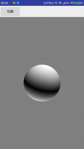
If we continue to use the conical shader, we will get such a ball:
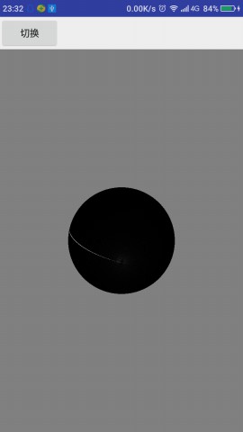
It doesn't look much like a ball. If it weren't for a white line, it wouldn't be a ball. We need to modify the lower vertex shader to give it a three-dimensional feel. Modify the vertex shader to:
uniform mat4 vMatrix;
varying vec4 vColor;
attribute vec4 vPosition;

void main(){
    gl_Position=vMatrix*vPosition;
    float color;
    if(vPosition.z>0.0){
        color=vPosition.z;
    }else{
        color=-vPosition.z;
    }
    vColor=vec4(color,color,color,1.0);
}
Run it, we get the following results, so that we can say it's a ball.