Links to the original text[ http://blog.chinaunix.net/uid-28623414-id-3618965.html]
Related documents
kernel/arch/arm/mach-rk2928/board-rk2926-sdk.c
kernel/drivers/video/backlight/rk2818_backlight.h
kernel/drivers/video/backlight/rk29_backlight.c
I. Driving Device Model
Like most of our commonly used drivers, PWM is also a Platform-type device driver. Related to this, we will need to provide the corresponding Platform Device. Platform Device is declared and registered in a board file. When the platform bus matches Device and Driver, we will get Platform Device registered in the system in advance in Driver, and then initialize and control it.
II. Registration of Backlight Equipment
  /***********************************************************
    * rk30 backlight
    ************************************************************/
    #ifdef CONFIG_BACKLIGHT_RK29_BL
    //Used to describe the ID of the pwm device, through this macro to switch the channel of pwm (2926 supports 3 pwm and shares one clock)
    #define PWM_ID 0
    #define PWM_MUX_NAME GPIO0D2_PWM_0_NAME
    #define PWM_MUX_MODE GPIO0D_PWM_0
    #define PWM_MUX_MODE_GPIO GPIO0D_GPIO0D2
    #define PWM_GPIO RK2928_PIN0_PD2
    #define PWM_EFFECT_VALUE 0

    #if defined(V86_VERSION_1_1)
    #define LCD_DISP_ON_PIN
    #endif

    #ifdef LCD_DISP_ON_PIN
    #if defined(V86_VERSION_1_1)
    #define BL_EN_PIN RK2928_PIN3_PC1
    #define BL_EN_VALUE GPIO_HIGH
    #define BL_EN_MUX_NAME GPIO3C1_OTG_DRVVBUS_NAME
    #define BL_EN_MUX_MODE GPIO3C_GPIO3C1
    #else
    #define BL_EN_PIN RK2928_PIN1_PB0
    #define BL_EN_VALUE GPIO_HIGH
    #endif
    #endif
    static int rk29_backlight_io_init(void)
    {
        int ret = 0;
        /* Setting GPIO Port as PWM Function */
        rk30_mux_api_set(PWM_MUX_NAME, PWM_MUX_MODE);

    #ifdef LCD_DISP_ON_PIN
        #if defined(V86_VERSION_1_1)
           rk30_mux_api_set(BL_EN_MUX_NAME, BL_EN_MUX_MODE);
    #endif

        /* Request GPIO Port */
        ret = gpio_request(BL_EN_PIN, NULL);
        if (ret != 0) {
            gpio_free(BL_EN_PIN);
        }

        /* Set GPIO port as output */
        gpio_direction_output(BL_EN_PIN, 0);

        /* Set output to highpoint flat */
        gpio_set_value(BL_EN_PIN, BL_EN_VALUE);
    #endif
        return ret;
    }

    static int rk29_backlight_io_deinit(void)
    {
        int ret = 0;
    #ifdef LCD_DISP_ON_PIN
        /* Pin status reversal */
        gpio_set_value(BL_EN_PIN, !BL_EN_VALUE);

        /* Release GPIO */
        gpio_free(BL_EN_PIN);
    #endif

        /* Set pin function to GPIO */
        rk30_mux_api_set(PWM_MUX_NAME, PWM_MUX_MODE_GPIO);

        #if defined(V86_VERSION_1_0) || defined(V86_VERSION_1_1)
        #if defined(CONFIG_MFD_TPS65910)
        if(g_pmic_type == PMIC_TYPE_TPS65910)
        {
            gpio_direction_output(PWM_GPIO, GPIO_HIGH);
        }
        #endif
        #endif

        return ret;
    }

    static int rk29_backlight_pwm_suspend(void)
    {
        int ret = 0;
        rk30_mux_api_set(PWM_MUX_NAME, PWM_MUX_MODE_GPIO);
        if (gpio_request(PWM_GPIO, NULL)) {
            printk("func %s, line %d: request gpio fail\n", __FUNCTION__, __LINE__);
            return -1;
        }
        #if defined(CONFIG_MFD_TPS65910)
         if (pmic_is_tps65910() )
         #if defined(V86_VERSION_1_0) || defined(V86_VERSION_1_1)
         gpio_direction_output(PWM_GPIO, GPIO_HIGH);
         #else
         gpio_direction_output(PWM_GPIO, GPIO_LOW);
         #endif
        #endif
        #if defined(CONFIG_REGULATOR_ACT8931)
         if (pmic_is_act8931() )
         gpio_direction_output(PWM_GPIO, GPIO_HIGH);
        #endif
    #ifdef LCD_DISP_ON_PIN
        gpio_direction_output(BL_EN_PIN, 0);
        gpio_set_value(BL_EN_PIN, !BL_EN_VALUE);
    #endif

        return ret;
    }

    static int rk29_backlight_pwm_resume(void)
    {
        gpio_free(PWM_GPIO);
        rk30_mux_api_set(PWM_MUX_NAME, PWM_MUX_MODE);
    #ifdef LCD_DISP_ON_PIN
        msleep(30);
        gpio_direction_output(BL_EN_PIN, 1);
        gpio_set_value(BL_EN_PIN, BL_EN_VALUE);
    #endif
        return 0;
    }

    /* Setting Backlight Information Structure */
    static struct rk29_bl_info rk29_bl_info = {
        .pwm_id = PWM_ID,
        .min_brightness = 40,//modefy by logan for make backlight lower
        .bl_ref = PWM_EFFECT_VALUE,
        .io_init = rk29_backlight_io_init,
        .io_deinit = rk29_backlight_io_deinit,
        .pwm_suspend = rk29_backlight_pwm_suspend,
        .pwm_resume = rk29_backlight_pwm_resume,
    };

    /* Setting Backlight Device (Platform Type) Structure */
    static struct platform_device rk29_device_backlight = {
        .name = "rk29_backlight",
        .id = -1,
        .dev = {
            .platform_data = &rk29_bl_info,
        }
    };

    #if defined(V86_VERSION_1_0) || defined(V86_VERSION_1_1) //for v86 to modify flash lcd when startup
    static int __init set_pwm_gpio_high(void)
    {
            printk("%s, xhc", __func__);
            rk30_mux_api_set(PWM_MUX_NAME, PWM_MUX_MODE_GPIO);
        if (gpio_request(PWM_GPIO, NULL)) {
            printk("func %s, line %d: request gpio fail\n", __FUNCTION__, __LINE__);
            return -1;
        }
        gpio_direction_output(PWM_GPIO, GPIO_HIGH);
            gpio_free(PWM_GPIO);
            return 0;
    }
    core_initcall(set_pwm_gpio_high);
    #endif

    #endif
As you can see from the above code, in fact, the core content just fills in the structure of a Platform device. Backlight information is stored in Platform_data (void * type). In the initialization of backlight information structure, the default PWM channel and callback functions such as initialization, anti-initialization, dormancy and recovery are set. Among them, the most important is the initialization function. In it, the selection of PWM function and the application of IO port are completed. This is necessary for us to complete the PWM function.
    static struct platform_device *devices[] __initdata = {
    #ifdef CONFIG_FB_ROCKCHIP
        &device_fb,
    #endif
    #ifdef CONFIG_LCDC_RK2928
        &device_lcdc,
    #endif
    #ifdef CONFIG_BACKLIGHT_RK29_BL
        &rk29_device_backlight,
    #endif
    #ifdef CONFIG_ION
        &device_ion,
    #endif
    #ifdef CONFIG_SND_SOC_RK2928
        &device_acodec,
    #endif
    #ifdef CONFIG_BATTERY_RK30_ADC_FAC
        &rk30_device_adc_battery,
    #endif
    };
    static void __init rk2928_board_init(void)
    {
            store_boot_source();
        gpio_request(POWER_ON_PIN, "poweronpin");
        gpio_direction_output(POWER_ON_PIN, GPIO_HIGH);

        pm_power_off = rk2928_pm_power_off;

        rk30_i2c_register_board_info();
        spi_register_board_info(board_spi_devices, ARRAY_SIZE(board_spi_devices));
        platform_add_devices(devices, ARRAY_SIZE(devices));

    #ifdef CONFIG_WIFI_CONTROL_FUNC
            rk29sdk_wifi_bt_gpio_control_init();
    #endif
    }
Next, we can see that our backlight device is registered in the Platform_device array named devices, and finally added to the list of platform devices through platform_add_devices in the rk2928_board_init function to match the corresponding driver registration. The match is based on our device name (.name = rk29_backlight).
After the system starts, various device drivers are loaded, and when there is a driver with the same name as the device we just registered, they are associated and the probe function in the driver is executed. In the backlight driver, we can see that the type of driver is platform_driver, and the corresponding driver name is also "rk29_backlight":
    static struct platform_driver rk29_backlight_driver = {
        .probe    = rk29_backlight_probe,
        .remove = rk29_backlight_remove,
        .driver    = {
            .name    = "rk29_backlight",
            .owner    = THIS_MODULE,
        },
        .shutdown    = rk29_backlight_shutdown,
    };
When the name matches, the probe callback function in the driver is executed:
    static int rk29_backlight_probe(struct platform_device *pdev)
    {
        int ret = 0;

        /* Getting Backlight Information for Registration */
        struct rk29_bl_info *rk29_bl_info = pdev->dev.platform_data;
        u32 id = rk29_bl_info->pwm_id;
        u32 divh, div_total;
        unsigned long pwm_clk_rate;

        //Backlight properties
        struct backlight_properties props;
        int pre_div = PWM_APB_PRE_DIV;

        if (rk29_bl) {
            printk(KERN_CRIT "%s: backlight device register has existed \n",
                    __func__);
            return -EEXIST;
        }

        if (!rk29_bl_info->delay_ms)
            rk29_bl_info->delay_ms = 100;

        if (rk29_bl_info->min_brightness < 0 || rk29_bl_info->min_brightness > BL_STEP)
            rk29_bl_info->min_brightness = 52;

        if (rk29_bl_info && rk29_bl_info->io_init) {
            rk29_bl_info->io_init();
        }

        if(rk29_bl_info->pre_div > 0)
            pre_div = rk29_bl_info->pre_div;

        memset(&props, 0, sizeof(struct backlight_properties));
        props.type = BACKLIGHT_RAW;
        props.max_brightness = BL_STEP;

        /* Registered Backlight Equipment */
        rk29_bl = backlight_device_register("rk28_bl", &pdev->dev, rk29_bl_info, &rk29_bl_ops, &props);
        if (!rk29_bl) {
            printk(KERN_CRIT "%s: backlight device register error\n",
                    __func__);
            return -ENODEV;
        }

    #if defined(CONFIG_ARCH_RK29)
        pwm_clk = clk_get(NULL, "pwm");  /* Getting pwm clock */
    #elif defined(CONFIG_ARCH_RK30) || defined(CONFIG_ARCH_RK2928)
        if (id == 0 || id == 1)
            pwm_clk = clk_get(NULL, "pwm01");
        else if (id == 2 || id == 3)
            pwm_clk = clk_get(NULL, "pwm23");
    #endif
        if (IS_ERR(pwm_clk) || !pwm_clk) {
            printk(KERN_ERR "failed to get pwm clock source\n");
            return -ENODEV;
        }

        /* Get clock frequency (1485 000 000 on RK2926) */
        pwm_clk_rate = clk_get_rate(pwm_clk);

        /* The number of clocks per cycle after APB pre-dividing (RK2926, pre_div is 1000) */
        div_total = pwm_clk_rate / pre_div;

        /* According to the PWM frequency dividing factor, the number of one cycle clocks after frequency dividing is calculated. The frequency dividing coefficient is shown in the figure below. */
        div_total >>= (1 + (PWM_DIV >> 9));

        /* If the frequency dividing factor is too small, the default value is 1 if it is possible to be zero. */
        div_total = (div_total) ? div_total : 1;

        if(rk29_bl_info->bl_ref) {
            divh = 0;
        } else {
            divh = div_total;
        }

        /* Enabling pwm clock */
        clk_enable(pwm_clk);

        /* Reset and Set Frequency Dividing Value */
        write_pwm_reg(id, PWM_REG_CTRL, PWM_DIV|PWM_RESET);

        /* Set the LRC register to the total number of clock cycles */
        write_pwm_reg(id, PWM_REG_LRC, div_total);

        /* Set up HRC register, duty cycle HRC/LRC */
        write_pwm_reg(id, PWM_REG_HRC, divh);

        /* Set the initial value of the CNTR register to 0 */
        write_pwm_reg(id, PWM_REG_CNTR, 0x0);

        /* Enabling PWM and TIMER Enabling */
        write_pwm_reg(id, PWM_REG_CTRL, PWM_DIV|PWM_ENABLE|PWM_TIME_EN);

        rk29_bl->props.power = FB_BLANK_UNBLANK;
        rk29_bl->props.fb_blank = FB_BLANK_UNBLANK;

        /* Set the default brightness to 50% */
        rk29_bl->props.brightness = BL_STEP / 2;
        rk29_bl->props.state = BL_CORE_DRIVER1;

        /* Perform backlight delay update action */
        schedule_delayed_work(&rk29_backlight_work, msecs_to_jiffies(rk29_bl_info->delay_ms));

        /* Create Property Files */
        ret = device_create_file(&pdev->dev,&dev_attr_rk29backlight);
        if(ret)
        {
            dev_err(&pdev->dev, "failed to create sysfs file\n");
        }

        /* Register android hang and wake-up related functions */
        register_early_suspend(&bl_early_suspend);
        #ifdef CONFIG_LOGO_LOWERPOWER_WARNING
        if( 1 == system_lowerpower ){

               rk29_bl->props.brightness =5;
               mdelay (1500);
        }
        #endif

        printk("RK29 Backlight Driver Initialized.\n");
        return ret;
    }
From the above PWM_DIV (0 Other frequency division coefficients are analogous. 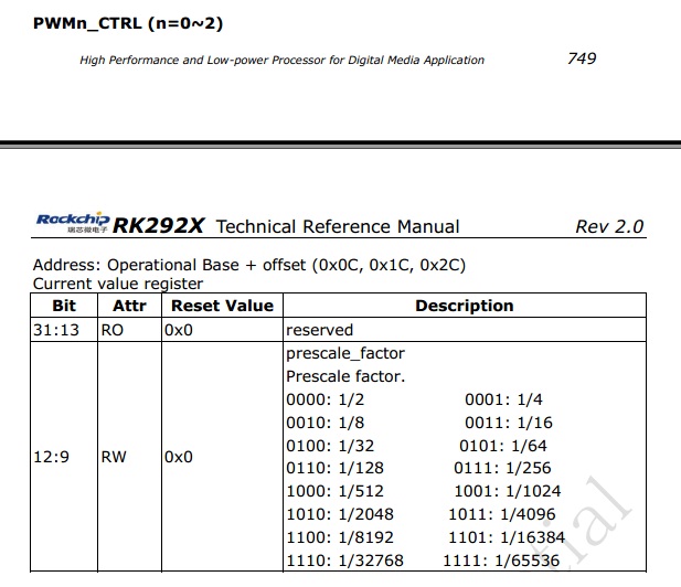
After opening the pwm, the default brightness is set to 50%, and the brightness is updated by the delay work queue. The function that actually updates brightness is:
 static int rk29_bl_update_status(struct backlight_device *bl)
{
    u32 divh,div_total;
    struct rk29_bl_info *rk29_bl_info = bl_get_data(bl);
    u32 id = rk29_bl_info->pwm_id;
    u32 ref = rk29_bl_info->bl_ref;
    int brightness = bl->props.brightness;

    if (suspend_flag)
        return 0;

    if (bl->props.brightness < rk29_bl_info->min_brightness && bl->props.brightness != 0)    /*avoid can't view screen when close backlight*/
        brightness = rk29_bl_info->min_brightness;

    if (bl->props.power != FB_BLANK_UNBLANK)
        brightness = 0;

    if (bl->props.fb_blank != FB_BLANK_UNBLANK)
        brightness = 0;

    if (bl->props.state & BL_CORE_DRIVER3)
        brightness = 0;

    /* Read the number of clock cycles in a pwm cycle */
    div_total = read_pwm_reg(id, PWM_REG_LRC);

    /* Calculate the number of normal clock cycles for setting high points by brightness value */
    if (ref) {
        divh = div_total*brightness/BL_STEP;
    } else {
        divh = div_total*(BL_STEP-brightness)/BL_STEP;
    }

    /* Update HRC to update duty cycle pwm output */
    write_pwm_reg(id, PWM_REG_HRC, divh);

    if ((bl->props.state & BL_CORE_DRIVER1) && brightness ==0 ){ //BL_CORE_DRIVER1 is the flag if backlight is closed.
        bl->props.state &= ~BL_CORE_DRIVER1;
        clk_disable(pwm_clk);
        if (rk29_bl_info->pwm_suspend)
            rk29_bl_info->pwm_suspend();
    }else if(!(bl->props.state & BL_CORE_DRIVER1) && brightness != 0){
        bl->props.state |= BL_CORE_DRIVER1;
        if (rk29_bl_info->pwm_resume)
            rk29_bl_info->pwm_resume();
        clk_enable(pwm_clk);
    }

    DBG("%s:line=%d,brightness = %d, div_total = %d, divh = %d state=%x \n",__FUNCTION__,__LINE__,brightness, div_total, divh,bl->props.state);
    return 0;
}
In practice, our screen is bright when the pwm output is low, that is to say, our duty cycle is the proportion of the out-of-screen state. So we need to adjust the output of bright state to 1-duty cycle, and each pwm cycle is LRC clock cycle, and the high-level cycle is HRC, so the duty cycle is HRC/LRC, corresponding to the actual situation, our effective brightness duty cycle should be 1-HRC/LRC= (LRC-HRC)/LRC. Mapping to BL_STEP is (BL_STEP-brightness)/BL_STEP. So if we want to adjust the time of a pwm cycle, we can adjust the value of LRC, and if we want to set the duty cycle, we can adjust the value of HRC. In our actual situation, when HRC is 0, the duty cycle is 1, while the effective brightness duty cycle is 100%, when HRC is LRC, the duty cycle is 100%, and the actual effective brightness duty cycle is 0. The ref variable above is used to identify whether the duty cycle of our current state corresponds to the true effective brightness, and classify and calculate according to it.
In fact, Ruixin Micro-Documents and Manual did not elaborate on the content of pwm. Most of the above is the analysis of the control code. If there are any mistakes, we hope that the experts will correct them.