A simple frequency meter is designed
Chip 51 has two timers which can be used for timing and counting. T1 is selected as counter to read the conversion times of high and low level. Select T0 as the timer, calculate the times of high and low level in 1S, and calculate the corresponding frequency through the algorithm. It is displayed on LCD screen.
ISIS simulation diagram is as follows 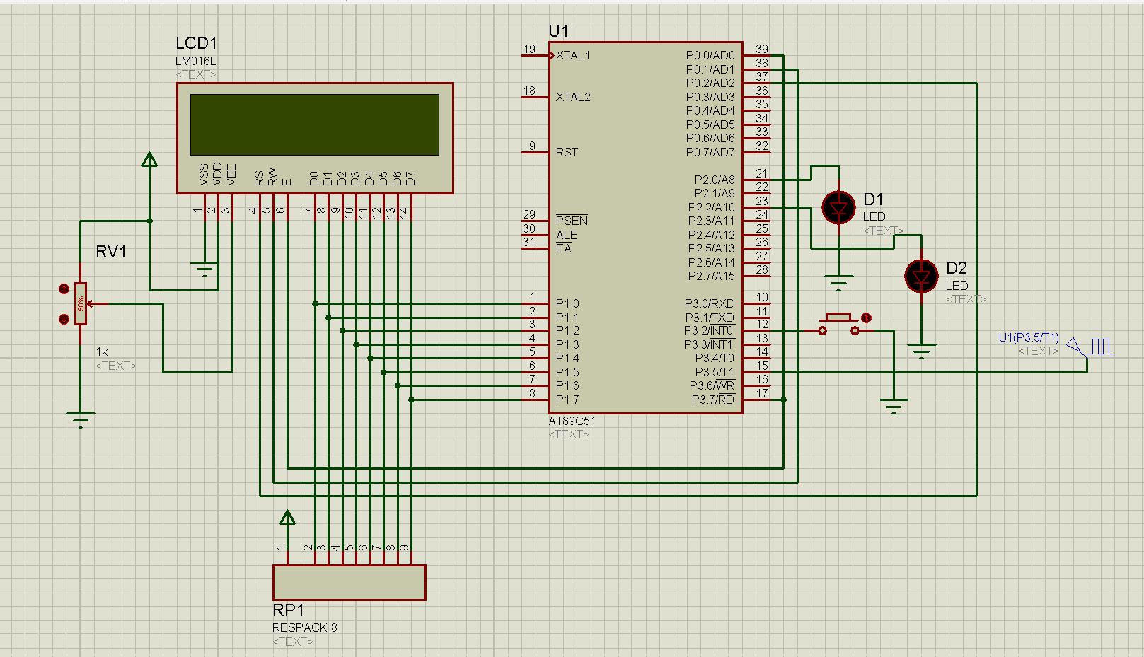
This is the configuration function of the LCD screen:
uchar num[]="0123456789";

sbit LCD_RS = P0^2;
sbit LCD_RW = P0^1;
sbit LCD_EN = P0^0;

void lcdWriteCmd(uchar cmd)       //LCD write function
{
  LCD_DATA = 0Xff;
  LCD_RS=0;
  LCD_RW=0;
  LCD_DATA=cmd;
  delay(1);
  LCD_EN=1;
  delay(1);
  LCD_EN=0;
}
void lcdWriteData(uchar dat)       //LCD write data
{
   LCD_RS=1;
   LCD_RW = 0;
   LCD_EN = 0;
   LCD_DATA=dat;
   delay(2);
   LCD_EN=1;
   delay(2);
   LCD_EN=0;
}
void clear()         //LCD clear LCD
{
  lcdWriteCmd(0x01);
  delay(5);
}
//LCD initialization
void lcdInit()
{
  lcdWriteCmd(0x38);
  delay(5);
  lcdWriteCmd(0x38);
  lcdWriteCmd(0x08);
  clear();
  lcdWriteCmd(0x06);
  delay(5);
  lcdWriteCmd(0x0c);
}
//LCD display function
void lcdDisplay(uint temp)
{
//  lcdWriteData(num[temp/100000%10]);
    lcdWriteData(num[temp/10000%10]);
    lcdWriteData(num[temp/1000%10]);
    lcdWriteData(num[temp/100%10]);
    lcdWriteData(num[temp/10%10]);
    lcdWriteData(num[temp%10]);
    lcdWriteData('H');
    lcdWriteData('Z');
    delay(400);
    clear();
}
After configuration, LCD can be used.
Next, we need to configure the timer and counter to collect the frequency:
void Time_Init(void)
{
    TH0 = 0X3C;
    TL0 = 0XB0;    //0x3cb0 50MS
    TR0 = 1;
}
void Interrupt_Init(void)
{
    IT0 = 1;
    EX0 = 1;
    ET0 = 1;
}
void Counter_Init(void)
{
    TH1 = 0X00;
    TL1 = 0X00;
    TR1 = 1;
}
Configure timer 0 as timing mode, Th0 = 0x3c; tl0 = 0xb0, 0x3CB0 = 15536
time = 65536-15536 = 50000 = 50ms. 50ms timer is interrupted once.
Then the interrupt function is called: the timer performs the Flag flag location 1 after interrupting the 20 interrupt, and the conversion times of the high and low level in the 1S acquisition time.
void T0_time() interrupt 1
{
    static uint i;
    i++;
    TH0 = 0X3C;
    TL0 = 0XB0;
    if (i == 20)    // 1s
    {
        Flag = 1;
        LED0 = !LED0;
        i = 0;
    }
}

void T1_Counter() interrupt 3
{
    times++;
}
Then process the collected data in the main function
void main()
{
    TMOD = 0X51;  //TO timer T1 counter
    Time_Init();
    Interrupt_Init();
    lcdInit();
    Counter_Init();
    ET1 = 1;
    EA = 1;

    while(1)
    {
        if (Flag)
        {
             Flag = 0;
             /*TL1 It is the data collected in the status, TH1 is also the data collected in the high position * 256, and times is the data overflowed * 65536*/
             ff = (int)((times*65536+TH1*256+TL1)/1.4);
             TH1 = 0X00;
             TL1 = 0X00;
             TR1 = 1;
        }
        lcdDisplay(ff);
    }
}
Such a simple frequency meter is ready. Enter ISIS for simulation and input 8KHZ 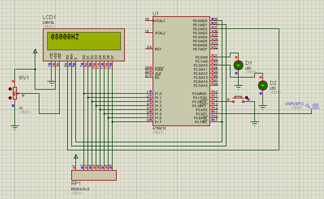
It can be seen that the frequency of 8KHZ is successfully detected.