4, Experimental conclusion
1. Experimental task 1
Contents of this part:
- Give the program task1.asm source code, and run screenshots
 1 assume cs:code, ds:data
 2
 3 data segment
 4     x db 1, 9, 3
 5     len1 equ $ - x
 6
 7     y dw 1, 9, 3
 8     len2 equ $ - y
 9 data ends
10
11 code segment
12 start:
13     mov ax, data
14     mov ds, ax
15
16     mov si, offset x
17     mov cx, len1
18     mov ah, 2
19  s1:mov dl, [si]
20     or dl, 30h
21     int 21h
22
23     mov dl, ' '
24     int 21h
25
26     inc si
27     loop s1
28
29     mov ah, 2
30     mov dl, 0ah
31     int 21h
32
33     mov si, offset y
34     mov cx, len2/2
35     mov ah, 2
36  s2:mov dx, [si]
37     or dl, 30h
38     int 21h
39
40     mov dl, ' '
41     int 21h
42
43     add si, 2
44     loop s2
45
46     mov ah, 4ch
47     int 21h
48 code ends
49 end start

- Answer question ①
① line27, when the assembly instruction loop s1 jumps, it jumps according to the displacement. Check the machine code through debug disassembly and analyze the jump displacement? (the displacement value is answered in decimal) from the perspective of the CPU, explain how to calculate the offset address of the instruction after the jump label s1.
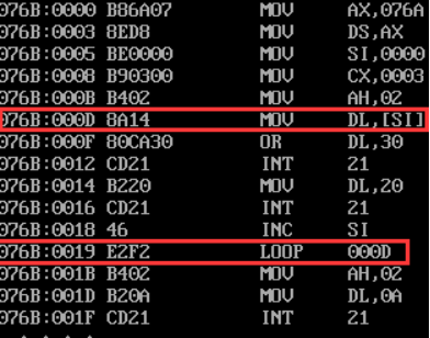
0Dh-1Bh=F2h is converted to decimal system as - 14, that is, the skip displacement is - 14
From the perspective of CPU, after the loop instruction,
Jump address = address of the first byte after the loop instruction + (address at "label" - address of the first byte after the loop instruction)
Simple calculation: jump address = 1Bh + (0Dh-1Bh) = 0Dh
In the computer, the offset is represented by an eight bit binary complement, and the subtraction of the complement is converted into addition for calculation. The actual calculation process is as follows:
1. First calculate the 8-bit offset - "address at label" - the address of the first byte after the loop instruction
0000 1101 (0D binary complement form)
0001 1011 (1B binary complement form)
1110 0101 (- binary complement form of 1B)
0000 1101-0001 1011 = 0000 1101 + 1110 0101 = 1111 0010 (binary complement form of F2)
In the computer, the machine code is represented by complement. You can see the machine code E2F2. F2 represents the calculated offset and is converted into decimal-14.
2. Add the offset and the first byte address after the loop instruction:
0001 1011 + 1111 0010 = 0000 1101 (binary complement form of 0D)
- Answer question ②
② line44. When the assembly instruction loop s2 jumps, it jumps according to the displacement. Check the machine code through debug disassembly and analyze the jump displacement? (the displacement value is answered in decimal) from the perspective of the CPU, explain how to calculate the offset address of the instruction after the jump label s2.
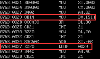
As shown in question ①, the offset = 29h-39h=f0h is converted to decimal - 16
The CPU angle will not be repeated.
2. Experimental task 2
Contents of this part:
- The program task2.asm source code is given
 1 assume cs:code, ds:data
 2
 3 data segment
 4     dw 200h, 0h, 230h, 0h
 5 data ends
 6
 7 stack segment
 8     db 16 dup(0)
 9 stack ends
10
11 code segment
12 start:
13     mov ax, data
14     mov ds, ax
15
16     mov word ptr ds:[0], offset s1
17     mov word ptr ds:[2], offset s2
18     mov ds:[4], cs
19
20     mov ax, stack
21     mov ss, ax
22     mov sp, 16
23
24     call word ptr ds:[0]
25 s1: pop ax
26
27     call dword ptr ds:[2]
28 s2: pop bx
29     pop cx
30
31     mov ah, 4ch
32     int 21h
33 code ends
34 end start
- After analysis, debugging and verification, register (ax) =? (bx) = (cx) =? Attach the screenshot of the debugging result interface.

(ax)=0021 (bx)=0026 (cx)=076C
① According to the jump principle of call instruction, it is analyzed theoretically that before the program executes to exit (line31), register (ax) =? Register (bx) =? Register (cx) =?
line 13-14 assigns the first address of the data segment to the ds register
line 16-18 take the IP of label s1 and store it in ds[0] address,
Take the IP labeled s2 and store it in the first address of the next byte, that is, ds[2] address,
Take the first address of cs segment and store it in the first address of the next byte, namely ds[4]
line 20-23 assigns the first address of the stack segment to the ss register and points the stack segment pointer to the top of the stack
line 24 stacks the IP address of the next statement and transfers it to the address pointed to by ds[0]. It can be seen from the above that it is the s1 label address
line 25 assigns the data pointed to by the current stack top pointer to bx. It can be seen from the above that it is the s1 label IP address
The line 27 program continues to execute downward, putting the next statement IP on the stack, and then CS on the stack. The program jumps to the address pointed to by ds[2], that is, the s2 label address
line 28 assigns the data pointed to by the current stack top pointer to bx, that is, the current address CS value
line 28 assigns the data pointed to by the current stack top pointer to cx, that is, the current address IP value
② Assemble and link the source program to get the executable program task2.exe. Use debug to debug, observe and verify debugging
Whether the results are consistent with the theoretical analysis results.
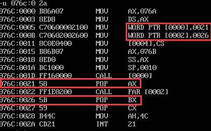
It can be seen from the disassembly of the source program that the address of s1 labeled at line16 is 0021, which is consistent with the location of s1 labeled below. The same is true for line17.
Before the program is executed, 16 bytes are pre stored in the stack, all of which are 0.

Step to line25, and the data in the stack is:

It can be seen that 0021 enters the stack. At the same time, because of the single-step execution of the protection site, the CS and IP values of the next command are also stored in the stack.
Continue to line 27. The data in the stack is:

You can see that the IP and CS values of the next instruction are stacked.
The program continues to line29, and the results are as follows:

The results are consistent with the theoretical analysis.
3. Experimental task 3
Contents of this part:
- The program source code task3.asm is given
 1 assume cs:code, ds:data
 2 data segment
 3     x db 99, 72, 85, 63, 89, 97, 55
 4     len equ $- x
 5 data ends
 6
 7 code segment
 8 start:
 9     mov ax, data
10     mov ds, ax
11     mov si, offset x
12     mov cx, len
13     mov bl,10
14
15  s1:mov ah,0
16     mov al, [si]
17     div bl
18     or al,30h
19     mov dh,al;Deposit quotient
20     or ah,30h
21     mov bh,ah;Residual
22
23     mov ah,2
24     ;Output quotient
25     mov dl,dh
26     int 21h
27     ;Output remainder
28     mov dl,bh
29     int 21h
30     ;Output space
31     mov dl, ' '
32     int 21h
33
34     inc si
35     loop s1
36
37    mov ah,4ch
38    int 21h
39 code ends
40 end start
- Screenshot of running test

4. Experimental task 4
Contents of this part:
- The program source code task4.asm is given
 1 assume cs:code,ds:data
 2
 3 data segment
 4     str db 'try'
 5     len equ $-str
 6 data ends
 7
 8 code segment
 9 start:
10     mov ax,data
11     mov ds,ax
12
13     mov ax,0b800h
14     mov es,ax
15     mov bx,0h;first line
16
17     mov si,offset str
18     mov cx,len
19 s1:
20     mov dl,[si];Low storage character Ascii code
21     mov es:[bx],dl
22     mov dl,2h;set a property
23     mov es:[bx+1],dl;Property is placed in the high-order address of the display address
24
25     add bx,2
26     inc si
27     loop s1
28
29     mov bx,0f00h;Line 25
30     mov cx,len
31     mov si,offset str
32 s2:
33     mov dl,[si];Low storage character Ascii code
34     mov es:[bx],dl
35     mov dl,4h;set a property
36     mov es:[bx+1],dl;Property is placed in the high-order address of the display address
37
38     add bx,2
39     inc si
40     loop s2
41
42
43     mov ah,4ch
44     int 21h
45 code ends
46 end start
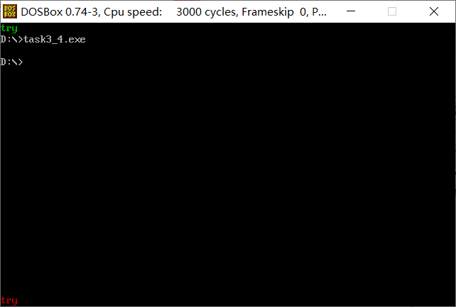
- Screenshot of running test
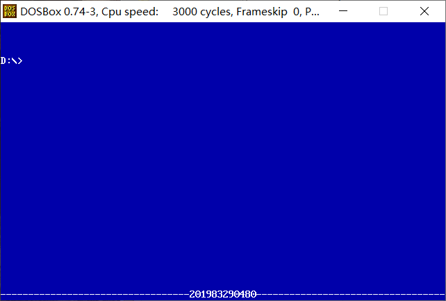
5. Experimental task 5
Contents of this part:
- The program source code task5.asm is given
 1 assume cs:code,ds:data
 2
 3 data segment
 4     stu_no db '201983290480'
 5     len = $-stu_no
 6 data ends
 7
 8 code segment
 9 start:
10     mov ax,data
11     mov ds,ax
12
13     mov ax,0b800h
14     mov es,ax
15
16     mov bx,0
17     mov cx,1920
18     call s1
19
20     mov bx,0f00h
21 Tos2: mov cx,34
22     call s2
23
24     mov si,offset stu_no
25     mov cx,len
26     mov bx,0f44h
27     call s3
28
29     mov ah,4ch
30     int 21h
31
32  s1:
33     mov dl,' '
34     mov es:[bx],dl
35     mov dl,1fh
36     mov es:[bx+1],dl
37     add bx,2
38     loop s1
39     ret
40
41 s2:
42     mov dl,'-'
43     mov es:[bx],dl
44     mov dl,1fh
45     mov es:[bx+1],dl
46     add bx,2
47     loop s2
48     ret
49
50 s3:
51     mov dl,[si]
52     mov es:[bx],dl
53     mov dl,1fh
54     mov es:[bx+1],dl
55     add bx,2
56     inc si
57     cmp cx,1;If=1,Jump
58     je Tos2
59     loop s3
60     ret
61
62 code ends
63 end start
- Screenshot of running test
5, Experimental summary
Summary of knowledge points:
1.EQU pseudo instruction connects a symbol name with an integer expression or an arbitrary text. It has three formats:
name EQU expression
name EQU symbol
name EQU <text>
In the first format, expression must be a valid integer expression. In the second format, symbol is an existing symbol name, which has been defined with = or EQU. In the third format, any text can appear in <... >. When the assembler encounters name later in the program, it uses integer value or text to replace the symbol.
Unlike the = directive, symbols defined with EQU cannot be redefined in the same source code file. This restriction prevents existing symbols from being inadvertently assigned new values.
2.$
"$" yes assembly language A predefined symbol in, which is equivalent to the current offset value of the segment currently being assembled. For example, "$" in eg: instruction "jmp $+3" indicates the current offset value of this instruction in the code segment Offset.
eg, that is, "jmp $+3", means to jump forward to a place 3 bytes away from the instruction. If "jmp $-3", it means to jump back to a place 3 bytes away from the instruction.
In assembly, it is the flag of the end of the string
For example: DATA SEGMENT
MES1 'HELLO',0AH,0DH,'$'