preface
1. Dynamic routing RIP configuration
2. Divide different network segments
3. Configure single arm circuit for R1 and R4 respectively
preface
1, Experimental content
catalogue
2, Experimental topology
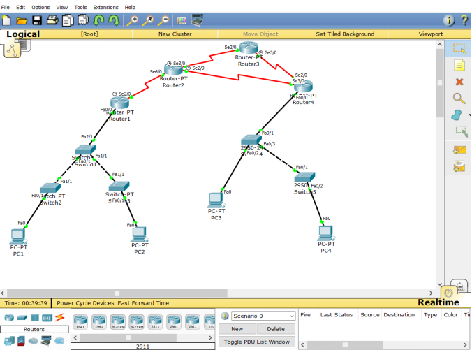
3, Implementation steps
Train of thought I
This is also the author's idea. Single arm routing + extended ACL (access control table). That is, configure single arm routing with route R1 and route R4, and then configure ACLS for f 0/0.1 and f 0/0.2 (the same as R4) of R1. Well, I won't say much. Let's start!
1. Dynamic routing RIP configuration
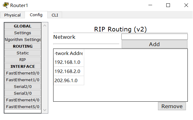
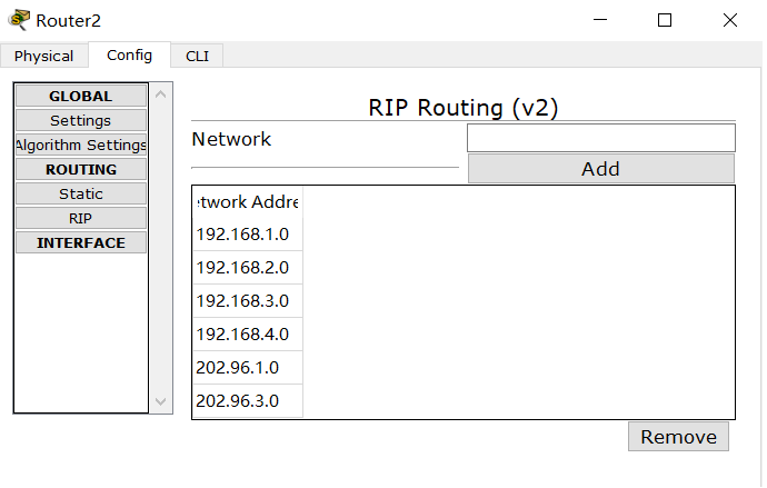
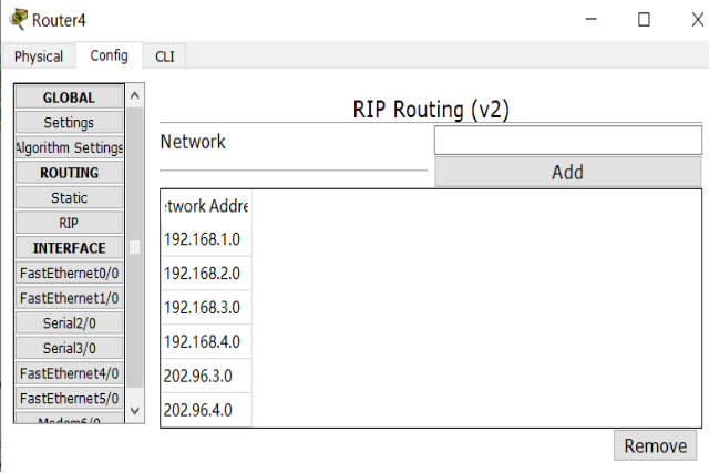
2. Divide different network segments
f of switch 1 2 / 1 port and f 0/1 port of switch4 are set as trunk ports, provided that the left and right ports (the same as switch4) are classified into vlan2 and vlan3, as shown in the figure below
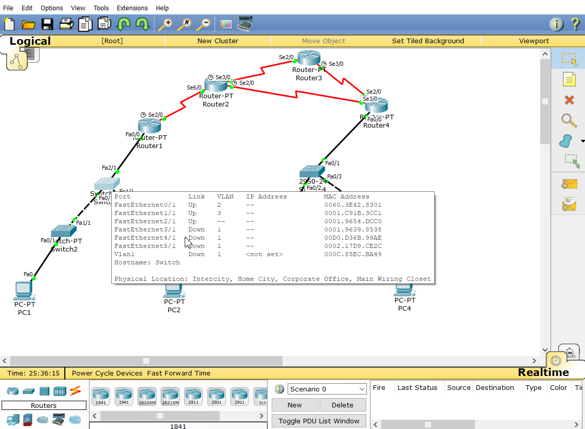
swich1
S1(config)#vlan 2
S1(config-vlan)#name vlan2
S1(config-vlan)#vlan 3
S1(config-vlan)#name vlan3
S1(config-vlan)#int f0/1
S1(config-if)#switchport mode access
S1(config-if)#switchport access vlan 2
S1(config-vlan)#int f1/1
S1(config-if)#switchport mode access
S1(config-if)#switchport access vlan 3
S1(config-if)#int f2/1
S1(config-if)#switchport mode trunk
S1(config-if)#exit
The same is true for switch4 configuration
Host IP address:
| host name | IP address |
| PC1 | 192.168.1.1 |
| PC2 | 192.168.2.1 |
| PC3 | 192.168.3.1 |
| PC4 | 192.168.4.1 |
3. Configure single arm circuit for R1 and R4 respectively
Configure single arm routing for R1. Note that the IP here depends on your host gateway
R1(config-if)#int f0/0.1 / / create a new 0.1 branch from fa0/0
R1(config-subif)#encapsulation dot1Q 2 / / configure VLAN2 trunking
 agreement
R1(config-subif)#ip add 192.168.1.254 255.255.255.0
R1(config-if)#int f0/0.2 / / create a new 0.1 branch from fa0/0
R1(config-subif)#encapsulation dot1Q 3 / / configure VLAN2 trunking
 agreement
R1(config-subif)#ip add 192.168.2.254 255.255.255.0
This is the IP address of PC1 and the gateway and subnet mask
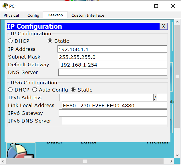
R1 route is as follows
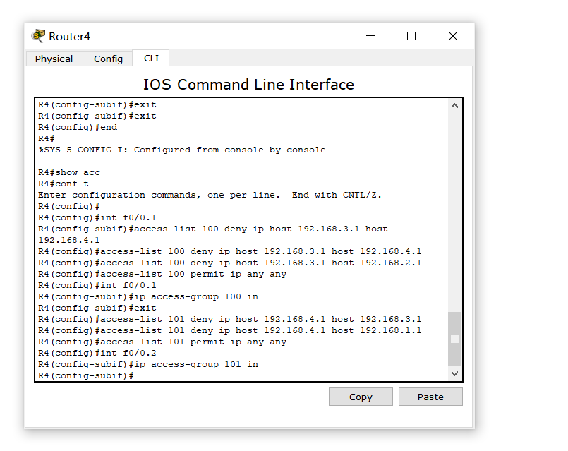
The following configuration is also carried out for R4 to avoid too long space. It is omitted here (lazy ing...)
4. ACL configuration
R1 configuration is mainly used to make PC1 and PC2 no longer ping
R1(config)#access-list 100 deny ip host 192.168.1.1 host 192.168.2.1
R1(config)#access-list 100 permit ip any any
R1(config)#access-list 101 deny ip host 192.168.2.1 host 192.168.1.1
R1(config)#access-list 101 permit ip any any
R1(config)#int f0/0.1
R1(config-if)#ip access-group 100 in
R1(config)#int f0/0.2
R1(config-if)#ip access-group 101 in
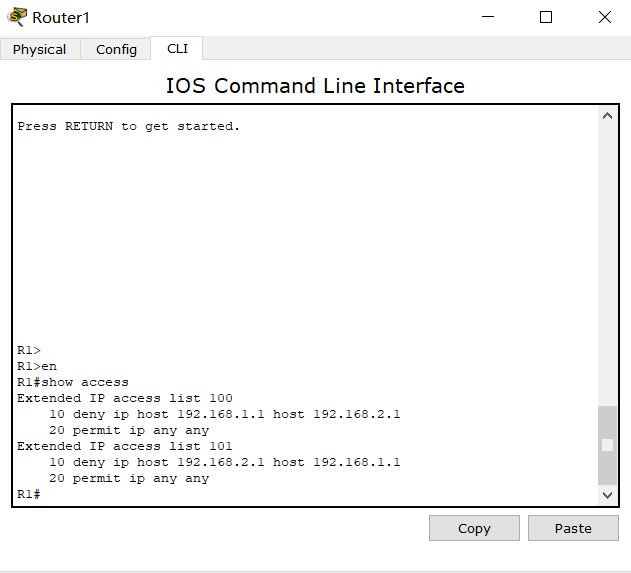
Note that you must be careful here (say important things three times). The command of allow IP any any any must be at the end, otherwise there will be big problems. Don't get the serial number of the list enabled in the port wrong , Finally, in privileged mode, enter: show acc to view
This is the R4 configuration. Here, we restrict the access of 192.168.2.1 and 192.168.1.1 to 192.168.2.1 and 192.168.1.1 addresses at the same time, that is, PC4ping does not work with PC1 and PC3ping does not work with PC2
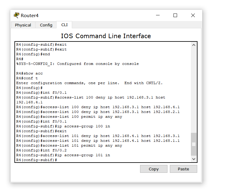
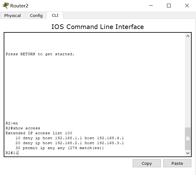
Finally, it's OK. The experiment is basically completed. PC1 can only ping with PC3, and PC2 can only ping with Pc4. However, some students may doubt that the restrictions on PC1 and PC2 accessing PC3 and Pc4 have not been configured. In fact, the students who have tried know that it is impossible to ping, but it is timeout, so they are not directly denied access, so they can continue to configure R2
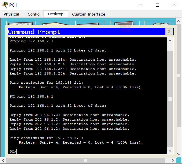
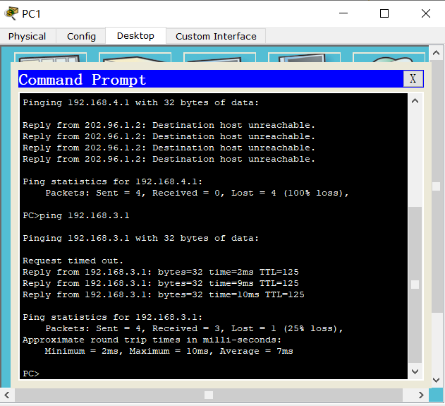
As expected, PC1 cannot ping PC2 and PC4, but can only ping PC3
5. Other ideas
Train of thought II
vlan + static nat access to external network + dynamic nat access to internal network (not implemented by the author)
sense thank various position large Guy of Read read
https://pan.baidu.com/share/init?surl=KigrAOUImtsDzrxRJFjd_Q
Extraction code: jpnq