1. A4988 introduction
A4988 has built-in decoder. We can control the stepping motor through two pins of the controller, one controls the rotation direction and the other controls the number of steps.
A4988 provides five different microstep controls:
- Full step
- Half step
- Quarter step
- Eight step
- Sixteenth step
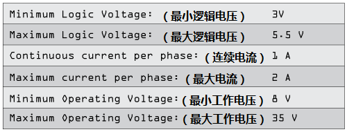
In addition, it is equipped with a potentiometer for regulating current output, overheating protection and overcurrent protection. The logic voltage range of A4988 is 3~5.5V. If better heat dissipation conditions are equipped, the maximum current of each phase can reach 2A. If there is no radiator, the continuous current of each phase should be controlled within 1A.
2. A4988 pin definition diagram and function description
-
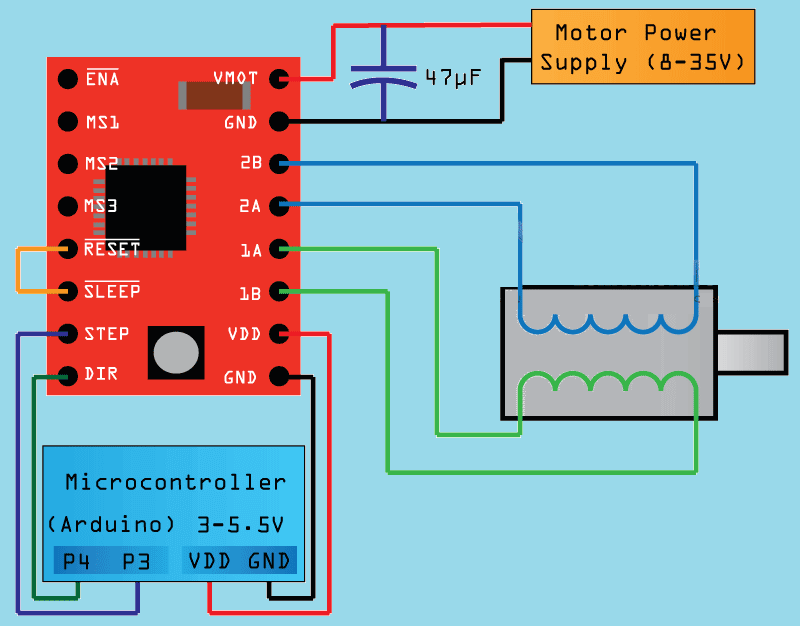
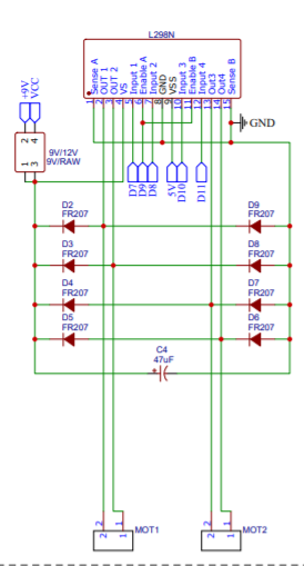
VMOT, GND: external power supply pin, which aims to provide sufficient power output for the motor. Power supply range: 8-35V. Here, a 47uf electrolytic capacitor is used to protect the driving board from the impact of instantaneous voltage.
-
VDD and GND: connect to 5V power supply and GND pin of Arduino control board.
-
1A and 1B: connected to one phase of the stepper motor, and pins 2A and 2B are connected to the other phase of the stepper motor.
-
STEP and DIR: connected to P3 and P4 pins of Arduino control board, which are mainly used to control the movement of motor. The Direction pin controls the rotation Direction, and the STEP pin is used to control the number of steps of motor rotation.
-
SLEEP: low level enables the module to be in SLEEP mode. When the motor is not working, it can minimize power consumption. It defaults to high level.
-
RESET: if the input of this pin is low, all micro step settings will be ignored.
Note: connect SLEEP and RESET pins to set the RESET pin to high level so that the module can be controlled.
-
ENABLE: used to turn on and off the output of the FET. It is turned on at low level and turned off at high level.
-
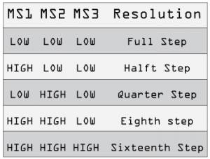
MS1, MS2 and MS3 pins are used for micro step setting.
- Full step
- Half step
- Quarter step
- Eight step
- Sixteenth step
As shown in the figure below:
In the full step mode of stepper motor, one step is 1.8 degrees, and one circle of 360 ° is 200 steps; If 1 / 16 step is used, one step is 0.1125 degrees, and a circle of 360 ° requires 3200 steps.
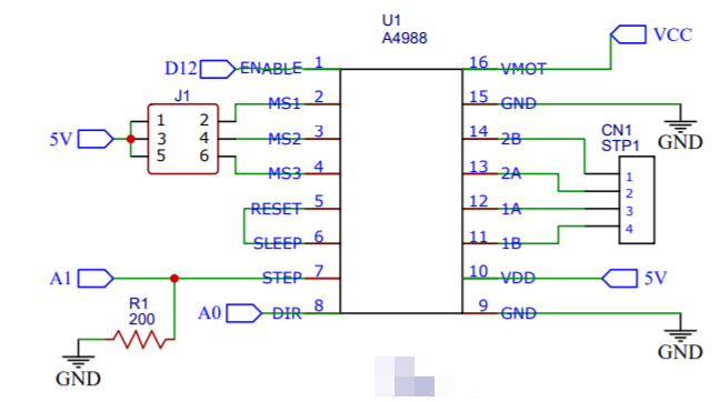
In the actual circuit design, the Arduino pin is set as follows:
1. In the circuit, the pins of MS1, MS2 and MS3 are pulled up by jumping cap (connector J1), and the micro step is set to 1 / 16 step (high, high).
2. The SLEEP and RESET pins are connected to set the RESET pin to high level so that the module can be controlled.
3. The 200 Ω resistor pulls the A1 pin down.
Four phase stepping motor
For two-phase bipolar hybrid stepping motor, it has four outgoing lines, which can be measured by multimeter. Among them, the red line and blue line have small resistance, and they are the same winding; Similarly, the resistance of green wire and black wire is small, and they are also the same winding. When wiring, just connect the corresponding output terminal on the driver of the stepper motor with the same winding, such as A + and A - in the above figure to the same winding, and B + and B - to another winding. After connection, start the machine for test run. If the steering is different from our requirements, just exchange A +, A - and B +, B -.
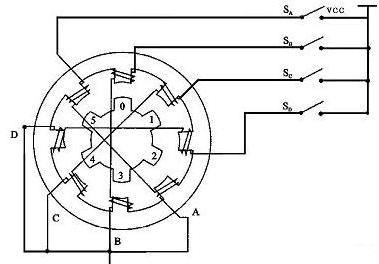
It is marked with A-B-C-D on the schematic diagram. Therefore, this stepping motor is called "four phase" stepping motor.
Assuming that phase B winding is closed and connected first, magnetic poles will be generated on the corresponding stator winding teeth. At this time, "0" and "3" of the rotor are closest to them, which will produce the strongest attraction.
If the winding of the stepping motor is energized in the order of phase B-phase C-phase D-phase A, the rotor of the stepping motor will run continuously in the counterclockwise direction.
Through the analysis, we can know that as long as a series of electric pulse signals are input to the electronic winding of the stepping motor, the rotor of the stepping motor will rotate continuously for an angle, which is the origin of the name of the stepping motor.
1B-1A-2A-2B
Red blue green black
Black green red blue
Problem 1: old vibration of stepping motor
Reason 1: the cable is connected incorrectly,
Cause 2: high speed vibration, low speed vibration
3. Arduino uses A4988 to control the motor code
// Arduino uses A4988 to control the motor code

#define Dir1pin   A0
#define Step1pin  A1
#define Enablepin 12
#define MSmodoule 3200

int x;

void setup()
{
  pinMode(Enablepin,OUTPUT); // Enable
  pinMode(Step1pin,OUTPUT); // Step
  pinMode(Dir1pin,OUTPUT); // Dir
  digitalWrite(Enablepin,LOW); // Set Enable low
}
void loop()
{
  digitalWrite(Dir1pin,HIGH); // Set Dir high

  for(x = 0; x < MSmodoule; x++) // Loop 200 times
  {
      digitalWrite(Step1pin,HIGH); // Output high
      delayMicroseconds(800); // Wait 1/2 a ms
      digitalWrite(Step1pin,LOW); // Output low
      delayMicroseconds(800); // Wait 1/2 a ms
    }
  delay(1000); // pause one second

  digitalWrite(Dir1pin,LOW); // Set Dir low

  for(x = 0; x < MSmodoule; x++) // Loop 2000 times
  {
      digitalWrite(Step1pin,HIGH); // Output high
      delayMicroseconds(800); // Wait 1/2 a ms
      digitalWrite(Step1pin,LOW); // Output low
      delayMicroseconds(800); // Wait 1/2 a ms
    }
    delay(1000); // pause one second
}
Summary:
1. D12 (-en) low level is to start the motor (enable). It seems that it can run without connection (but it still needs to be used if you want to control the start and shutdown of the motor);
2. A0(-dir) controls the direction with high and low levels;
3. A1(-step) drive the motor to rotate with high and low levels. Pay attention to the microsecond value of waiting in the middle interval. If it is too fast, the motor will not rotate with sound.
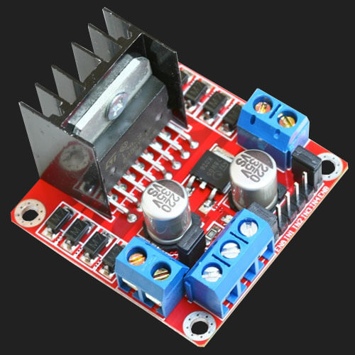
1. Introduction to L298N
L298N is a special drive integrated circuit and belongs to H-bridge integrated circuit. The difference between L298N and L293D is that the output current increases and the power increases.
Its output current is 2A, the maximum current is 4A and the maximum working voltage is 50V. It can drive inductive loads, such as high-power DC motor, stepping motor, solenoid valve and so on. In particular, its input can be directly connected with the single chip microcomputer, so it can be easily controlled by the single chip microcomputer.
When driving the DC motor, the stepping motor can be directly controlled, and the forward rotation and reverse rotation of the motor can be realized. To realize this function, only the logic level of the input terminal needs to be changed. In order to avoid the interference of the motor to the single chip microcomputer, this module adds an optocoupler for photoelectric isolation (the optocoupler transmits electrical signals with light as the medium, which has a good isolation effect on the input and output electrical signals), and the rectifier diode motor protection, so that the system can work stably and reliably.
4-channel control, tantalum (t) ǎ n) Capacitor voltage stabilization, optocoupler isolation, rectifier diode motor protection, overcurrent protection, alloy heat sink, digital and analog circuit line separation, motor current feedback and PWM speed regulation, motor double closed-loop control.
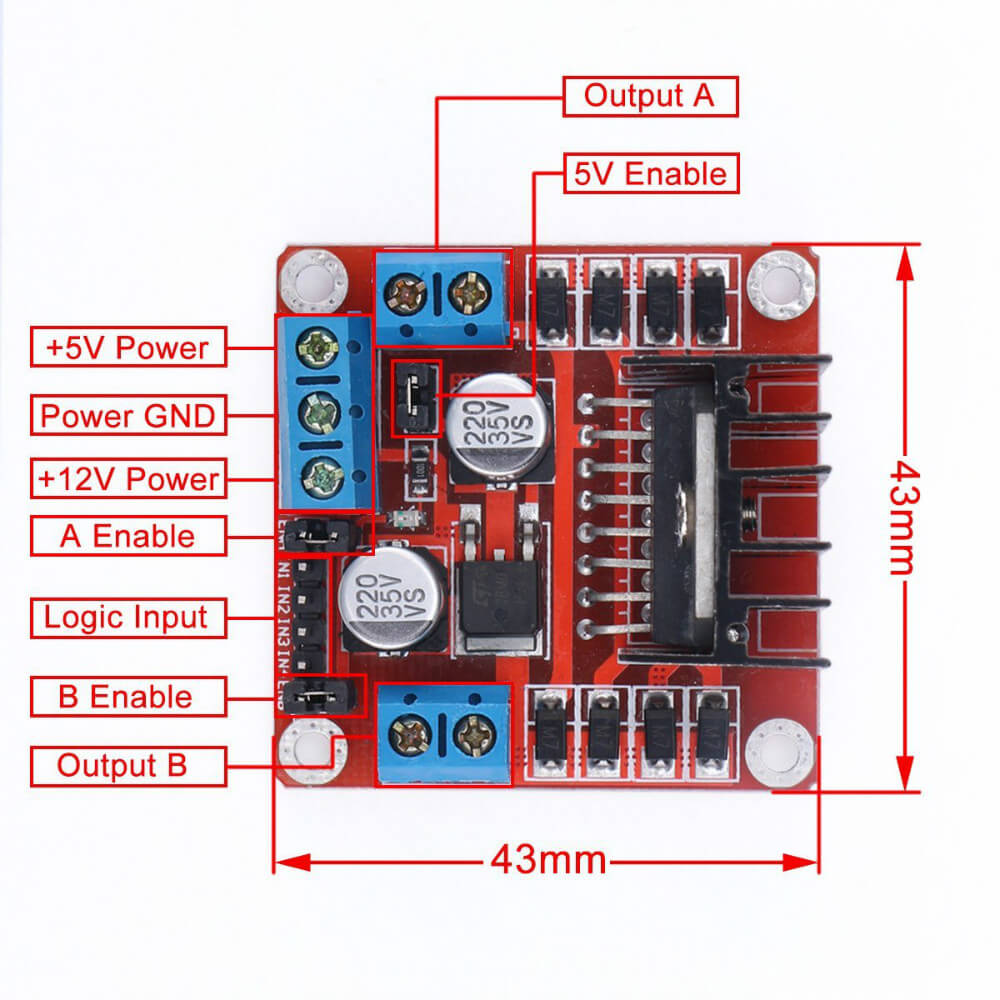
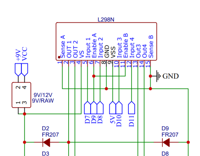
2. L298N appearance dimension and pin definition
-
Output A: connected to A + and A - of DC motor 1 or stepper motor;
-
Output B: connected to B + and B - of DC motor 2 or stepper motor;
-
5V Enable: when the input power supply is less than 12V, short circuit can provide 5V power output. If the input power supply is greater than 12V, please remove the jumper cap;
-
+5V Power: when the input power is less than 12V and 5V Enable is in short circuit state, it can provide + 5V Power output (refer to the label on the drive board for the actual position);
-
Power Gnd: power ground;
-
+12V Power: connect the motor power supply, maximum 35V. When the input voltage is greater than 12V, to ensure safety, please remove the jumper cap on the 5V Enble pin (refer to the label on the drive board for the actual position);
-
A / b enable: it can be used to input PWM pulse width modulation signal for speed regulation control of motor. (if speed regulation is not required, connect the two pins to 5V to make the motor work at the highest speed, i.e. short circuit the short-circuit cap)
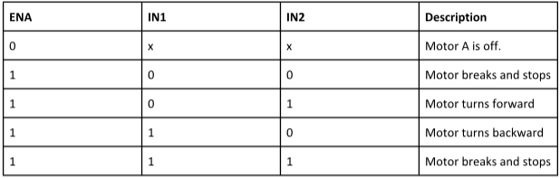
Realize the forward and reverse rotation function of the motor:
Motor M1 rotates forward, input signal terminal IN1 is connected to high level, and input terminal IN2 is connected to low level. (IF signal terminal IN1 is connected to low level and IN2 is connected to high level, motor M1 is reversed.)
Motor M2 rotates forward, input signal terminal IN3 is connected to high level, and input terminal IN4 is connected to low level. (otherwise, reverse)
PWM signal terminal A controls M1 speed regulation, and PWM signal terminal B controls M2 speed regulation. Refer to the following chart:
In the actual circuit design, the Arduino pin is set as follows:
3. Arduino uses L298N to control the motor code
// Arduino uses L298N to control the motor code
/*
Project Name: DC / stepper motor driver
 Function:
Author: Naiva
 Date: November 19, 2021
 Version: V1.0
*/

#define In1pin 7
#define In2pin 8
#define Speed_Motor  9
#define asingle A6


void setup() {
  Serial.begin(9600);
  pinMode(In1pin, OUTPUT);
  pinMode(In2pin, OUTPUT);
  pinMode(Speed_Motor, OUTPUT);
  pinMode(asingle, INPUT);
}

void loop() {

  int val = analogRead(asingle);
  val = map(val,0,1023,0,255);
  Serial.print("A6 Analog signals are:");
  Serial.println(val);

  analogWrite(Speed_Motor,val);
  digitalWrite(In1pin, HIGH);
  digitalWrite(In2pin, LOW);
  delay(10);
}
reference material
-
[1] Three terminal voltage stabilizing integrated circuit LM7805/LM7809 (LM78xx positive voltage LM79xx negative voltage series)
-
[2] L298N motor drive( Pin definition of motor drive board L298N)
-
[3] FR207 loss diode
-
[4] A4988 stepper motor drive module( Pin diagram and application of A4988)(Arduino+A4988 + stepper motor)
-
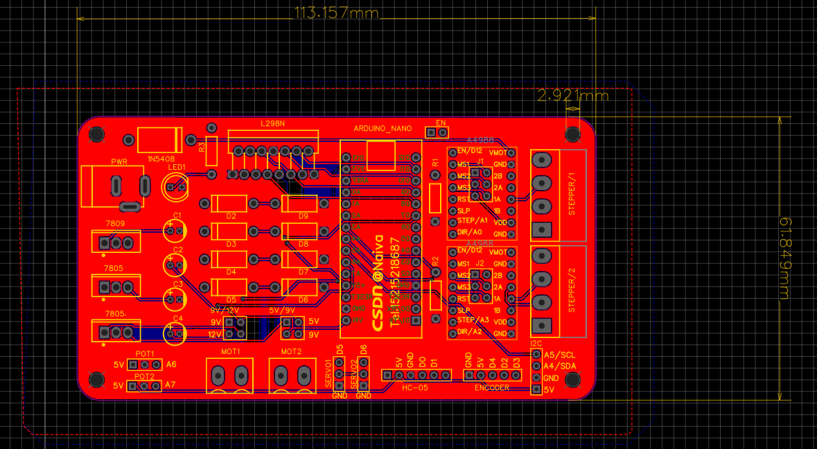
The circuit schematic diagram is as follows:
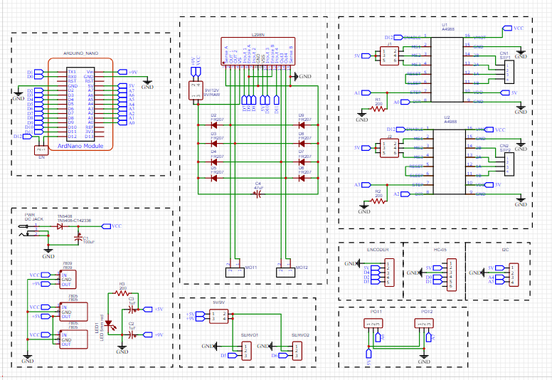
Attached source code:
/***************************************
Project Name: DC / stepper motor driver
 Function:
Author: Naiva
 Date: November 19, 2021
 Version: V1.0
*******************************************/
#define In1pin 7
#define In2pin 8
#define Speed_Motor  9
#define asingle A6

#define Dir1pin   A0
#define Step1pin  A1
#define Enablepin 12
#define MSmodoule 3200

void DC_motor1(){
  int val = analogRead(asingle);
  val = map(val,0,1023,0,255);
  Serial.print("A6 Analog signals are:");
  Serial.println(val);

  analogWrite(Speed_Motor,val);
  digitalWrite(In1pin, HIGH);
  digitalWrite(In2pin, LOW);
  delay(10);
  }
void Step_stepper1_forward(int delaytime){
  digitalWrite(Dir1pin,HIGH);     // Set direction high
  for(int i = 0; i < MSmodoule; i++)  // Number of cycles of MSmodoule
  {
      digitalWrite(Step1pin,HIGH);
      delayMicroseconds(800);     //Delay 800 microseconds
      digitalWrite(Step1pin,LOW);
      delayMicroseconds(800);
    }
  delay(delaytime);               //Delay 1 second

  }
void Step_stepper1_backward(int delaytime){
  digitalWrite(Dir1pin,LOW);      // Set direction
  for(int j = 0; j < MSmodoule; j++)  // 3200 cycles
  {
      digitalWrite(Step1pin,HIGH);
      delayMicroseconds(800);
      digitalWrite(Step1pin,LOW);
      delayMicroseconds(800);
    }
    delay(delaytime);             // delayed
  }
void Stop_DC_motor1(){
  digitalWrite(In1pin, LOW);
  digitalWrite(In2pin, LOW);
  delay(10);
  }
void Stop_stepper1(){
  digitalWrite(Step1pin,LOW);
  delayMicroseconds(800);
  digitalWrite(Step1pin,LOW);
  delayMicroseconds(800);
  }
void setup() {
  Serial.begin(9600);
  pinMode(In1pin, OUTPUT);
  pinMode(In2pin, OUTPUT);
  pinMode(Speed_Motor, OUTPUT);
  pinMode(asingle, INPUT);

  pinMode(Enablepin,OUTPUT); // Enable FET output
  pinMode(Step1pin,OUTPUT); // turn
  pinMode(Dir1pin,OUTPUT); // direction
  digitalWrite(Enablepin,LOW); // Low level on
  delayMicroseconds(800);
}

void loop() {
  DC_motor1();
  Stop_DC_motor1();
  Step_stepper1_forward(1000);
  Step_stepper1_backward(1000);
  Stop_stepper1();
}