How dare a small code farmer say he can't collect
Analog quantity - > digital quantity (ADC module)
Relationship between analog quantity and digital quantity of single chip microcomputer
The CPU circuit of 5V single chip microcomputer is binary. In the operation process, there are only two kinds of voltages: high level 5V and low level 0V. For the signal with continuous change of voltage or current, it needs to be transformed into a digital level signal that can be recognized by single chip microcomputer through analog-to-digital conversion circuit. MP3 is a distorted file saved by ADC sampling.
The method of converting analog quantity into digital quantity
When analog quantity becomes digital quantity, comparator is usually used for conversion. At present, there are two common methods: parallel comparison and successive comparison.
**Parallel comparator: * * the speed is relatively fast, but there are many components. The cost will be very high. Therefore, the practicability is not very extensive
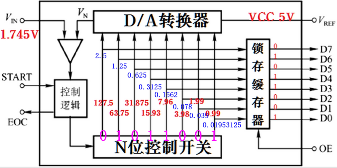
**Successive comparator: * * through feedback control, the result is converted after multiple operations. It has the advantages of low cost, simple components and easy to make high-precision converters, so it is widely used.
Concept of successive comparator ADC
A super good example to share with you
Let's play a game first: the dog egg took some peanuts and told you that if you want to eat, you have to guess how many there are first. Tell you the maximum is 255. When you guess, you can tell you more or less. So, how can we guess the number of peanuts as soon as possible?
When guessing, in order to facilitate the calculation, we add 0.5 peanuts.
==Step 1: = = guess 255 ÷ 2 + 0.5 = 128. The dog egg tells you that there is more (0).
Step 2: guess 128 ÷ 2 = 64. The dog egg tells you that there is less (1).
Step 3: guess (128 + 64) ÷ 2 = 96. The dog egg tells you that there is more (0).
Step 4: guess (96 + 64) ÷ 2 = 80. The dog egg tells you that there is less (1).
Step 5: guess (96 + 80) ÷ 2 = 88. The dog egg tells you that there is less (1).
Step 6: guess (96 + 88) ÷ 2 = 92. The dog egg tells you that there is more (0).
Step 7: guess (92 + 88) ÷ 2 = 90. The dog egg tells you that there is more (0).
Step 8: guess (90 + 88) ÷ 2 = 89. Dog egg tells you, guess right (?).
The result is: if 0.5 is not added, the result of the actual calculation formula is 88.65234375. In fact, 88.65 is smaller than 89, so it's 1
Rounding, 89 > 88.65, take= 1 ; The result is 0 1 0 1 1 0 1 = 89 = 0x59;
Register of STC internal ADC module
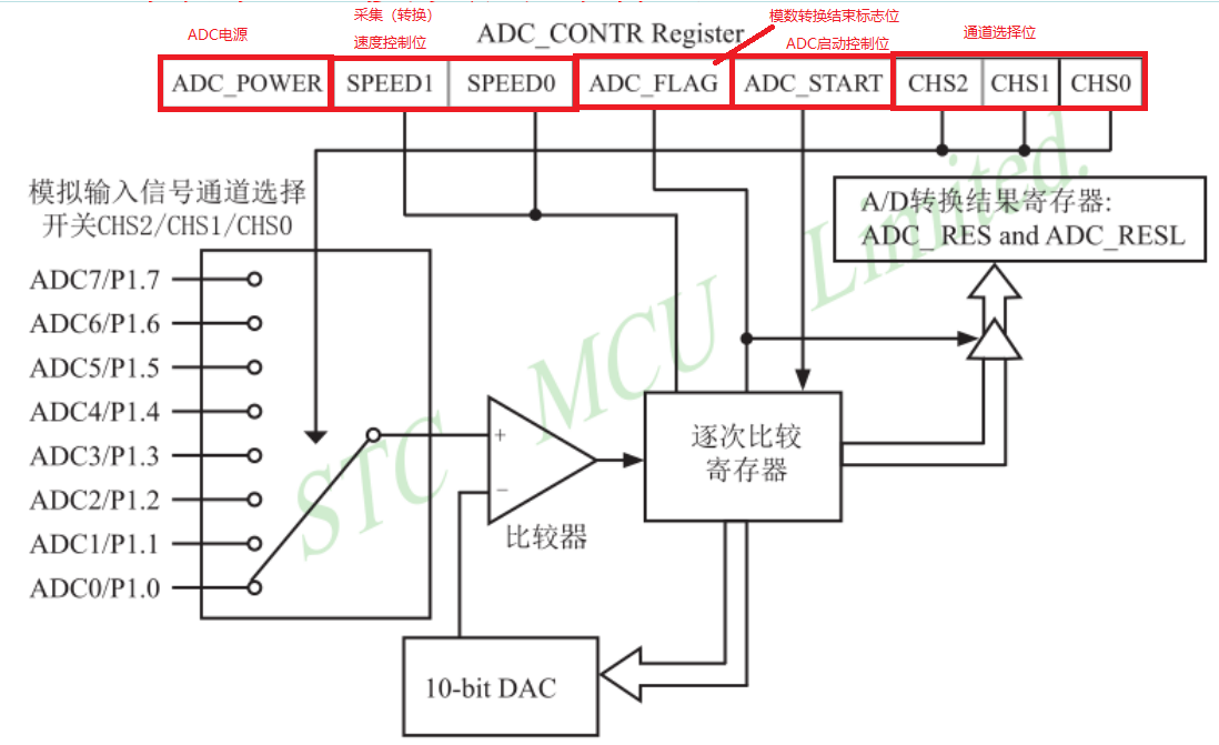
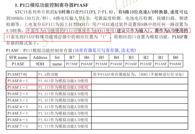
1. The ADC port is configured as ADC input mode or high resistance mode
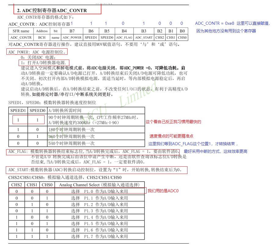
2.ADC control register: ADC_CONTR. Control power supply, conversion speed, flag bit, start bit, channel selection [2:0]
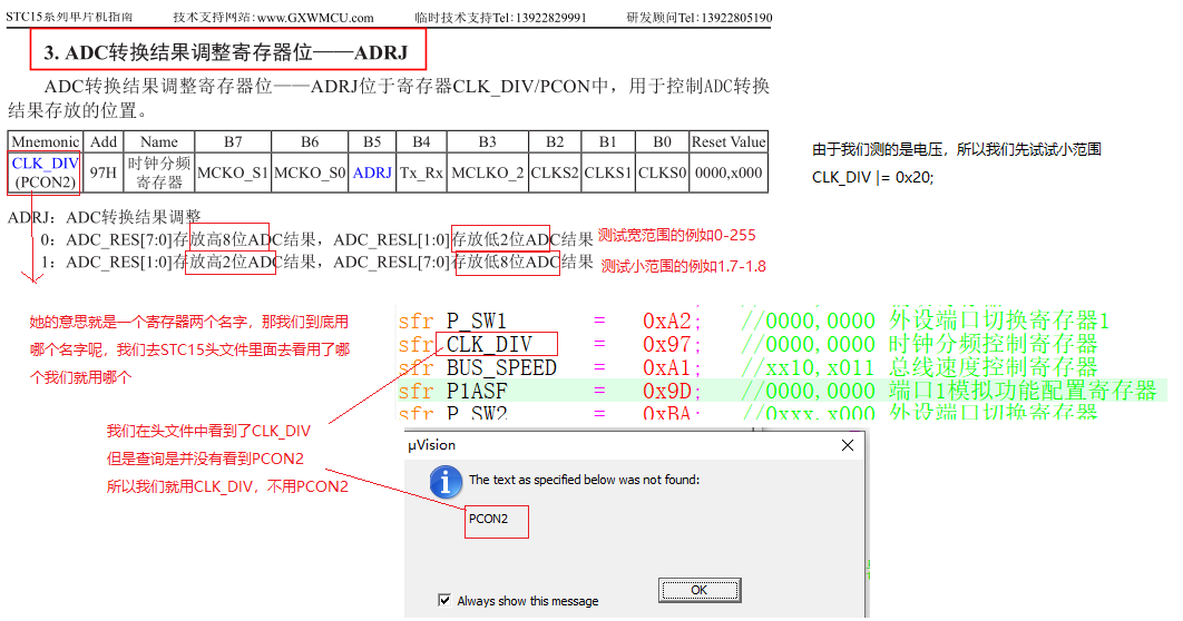
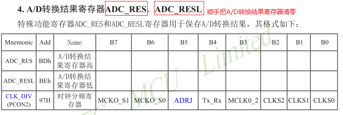
3.ADC sampling result output register_ RES,ADC_RESL. It can be [1:0] + [7:0], or [7:0] + [1:0]
4.ADC conversion, register IE related to interrupt
5. Auxiliary register AUXR1 mainly controls the storage format of result register
Here we need to collect the battery voltage (we use P1.0 to collect)
I'm going to use ADC0 to detect the battery voltage. It depends on the teacher's needs, and then display the display on the nixie tube. Because I've published the nixie tube blog before, you may still have some impression. You don't know Real nixie tube
P1M1 |= 0x01; P1M0 &= ~0x01;// P1.0 pin ADC0
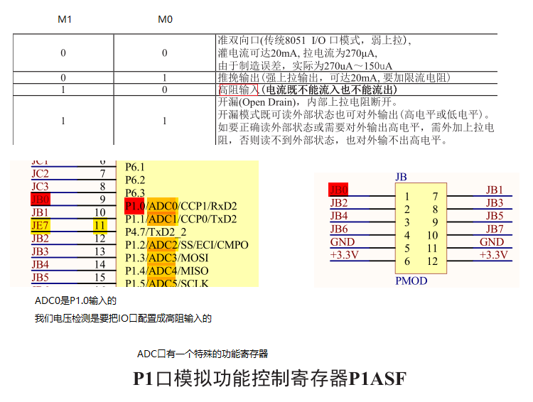
P1ASF |= 0x01;
CLK_DIV |= 0x20;
ADC_RES = 0;ADC_RESL = 0;
ADC initialization
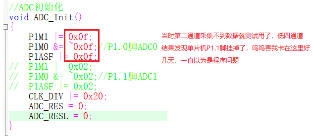
//ADC initialization
void ADC_Init()
{
	P1M1 |= 0x0f;
	P1M0 &= ~0x0f;//P1.0 pin ADC0
	P1ASF |= 0x0f;
//	P1M1 |= 0x02;
// 	P1M0 &= ~0x02;// P1.1 pin ADC1
//	P1ASF |= 0x02;
	CLK_DIV |= 0x20;
	ADC_RES = 0;
	ADC_RESL = 0;
}
ADC_CONTR = 0x88;
ADC read data underlying driver
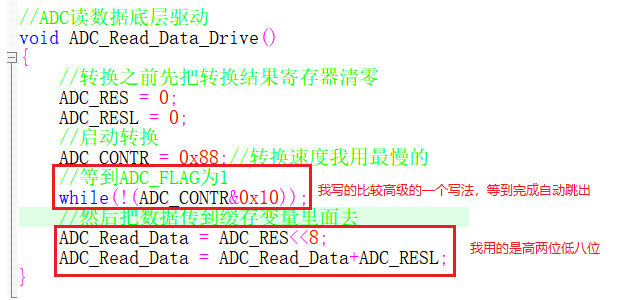
//ADC read data underlying driver
void ADC_Read_Data_Drive()
{
	//Clear the conversion result register before conversion
	ADC_RES = 0;
	ADC_RESL = 0;
	//Start conversion
	ADC_CONTR = 0x88;//I use the slowest conversion speed
	//Wait until ADC_FLAG is 1
	while(!(ADC_CONTR&0x10));
	//Then transfer the data to the cache variable
	ADC_Read_Data = ADC_RES<<8;
	ADC_Read_Data = ADC_Read_Data+ADC_RESL;
}
Demo video
Acquisition voltage
Acquisition voltage
ADC code
ADC_ Drive. C (there is also a filter function written by myself to stabilize the data) basically, this level can save two
#include "all.h"


//If we have data, we have to save it
u16 xdata ADC_Read_Data = 0;
u16 xdata ADC_Filter_Data = 0;

//ADC initialization
void ADC_Init()
{
	P1M1 |= 0x0f;
	P1M0 &= ~0x0f;//P1.0 pin ADC0
	P1ASF |= 0x0f;
//	P1M1 |= 0x02;
// 	P1M0 &= ~0x02;// P1.1 pin ADC1
//	P1ASF |= 0x02;
	CLK_DIV |= 0x20;
	ADC_RES = 0;
	ADC_RESL = 0;
}

//ADC read data underlying driver
void ADC_Read_Data_Drive()
{
	//Clear the conversion result register before conversion
	ADC_RES = 0;
	ADC_RESL = 0;
	//Start conversion
	ADC_CONTR = 0x88;//I use the slowest conversion speed
	//Wait until ADC_FLAG is 1
	while(!(ADC_CONTR&0x10));
	//Then transfer the data to the cache variable
	ADC_Read_Data = ADC_RES<<8;
	ADC_Read_Data = ADC_Read_Data+ADC_RESL;
}

//Global ADC filtered data structure pointer
ADC_Data* adc_filter;

//ADC filter data bottom driver
void ADC_Filter_Data_Drive()
{

	/*u16  ADC_Min = 0;
	u16  ADC_Max = 0;
	u16  ADC_Tmp = 0;
	u16  ADC_Result = 0;*/

	//Set two loop variables
	u8 i = 0;
	u8 j = 0;
	ADC_Filter_Data = 0;
	ADC_Read_Data_Drive();
	for(i = 0;i<4;i++)//Outer layer 8 cycles
	{
		adc_filter->ADC_Result = 0;
		adc_filter->ADC_Min =
		adc_filter->ADC_Max =
		ADC_Read_Data;
		for(j = 0;j<4;i++)//Inner layer 8 cycles
		{
			adc_filter->ADC_Tmp = ADC_Read_Data;
			if (adc_filter->ADC_Tmp < adc_filter->ADC_Min)
			{
				adc_filter->ADC_Result += adc_filter->ADC_Tmp;
				adc_filter->ADC_Min = adc_filter->ADC_Tmp;
			}
			else if (adc_filter->ADC_Tmp > adc_filter->ADC_Max)
			{
				adc_filter->ADC_Result += adc_filter->ADC_Tmp;
				adc_filter->ADC_Max = adc_filter->ADC_Tmp;
			}
			else
			{
				adc_filter->ADC_Result += adc_filter->ADC_Tmp;
			}
		}
		adc_filter->ADC_Result /= 4;
		ADC_Filter_Data += adc_filter->ADC_Result;
	}
	  ADC_Filter_Data /= 4;
}
ADC_Drive.h
#ifndef ADC_Drive
#define ADC_Drive

typedef struct ADC_Filter_Data
{
	u16  ADC_Min;      //ADC min
	u16  ADC_Max;      //ADC Max
	u16  ADC_Tmp;      //ADC temporary value
	u16  ADC_Result;   //ADC results
} ADC_Data;

//External declaration
extern void ADC_Init();
extern void ADC_Read_Data_Drive();
extern void ADC_Filter_Data_Drive();
extern u16 xdata ADC_Read_Data;
extern u16 xdata ADC_Filter_Data;
#endif