1, Hardware scheme
In this design, the light intensity is detected through the photosensitive resistance, and then processed by the A/D module PCF8591, the light intensity value is displayed on the liquid crystal in real time, and the light intensity value can be controlled by pressing the key. When the light is lower than the set threshold, a white highlight LED light is on for light supplement, and the light is higher than the set threshold, so it doesn't matter. The temperature value is detected by DS18B20 and displayed on 1602 LCD in real time. The temperature value can be set by pressing the key. When the temperature is lower than the set value, it is simulated by a yellow highlighted LED lamp.
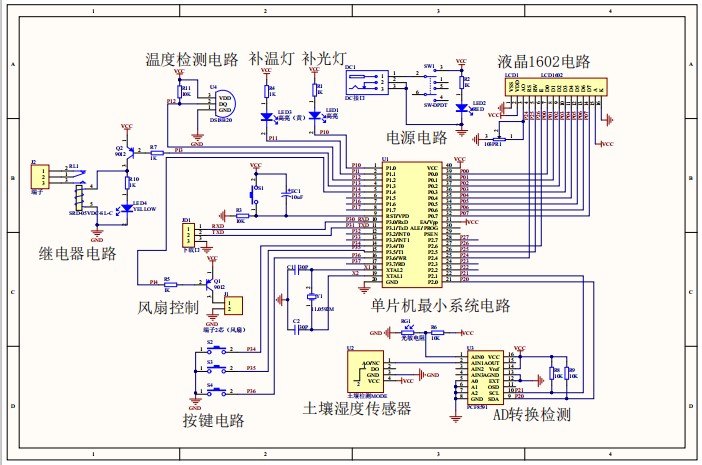
It is mainly composed of STC89C52 single chip microcomputer, LCD1602 liquid crystal display, light detection, soil humidity sensor, A/D sampling PCF8591, fan control, relay control, fill light, fill temperature light, key and power supply; As shown in the figure:

2, Design function
(1) The light intensity is detected through the photoresist, and then processed by the A/D module PCF8591, the light value is displayed on the liquid crystal in real time, and the light threshold can be set by pressing the key. When the illumination is lower than the set threshold, the highlighted LED will be on for light supplement, otherwise it will be turned off.
(2) The temperature value is detected by DS18B20 and displayed on 1602 LCD in real time. The temperature threshold can be set by pressing the key. When the temperature is lower than the set value, the temperature supplement lamp will be turned on, otherwise it will be turned off; When the temperature exceeds the set value, the fan rotates.
(3) The soil humidity is detected by the soil humidity sensor, the humidity value is displayed on the LCD, and the key is pressed to set the humidity threshold. When the soil humidity is less than the set threshold, the relay is opened, and the relay can be connected with an external water pump; Otherwise, the relay will not operate.
3, Design schematic diagram
(1) The schematic diagram is mainly designed by AD software, as shown in the figure:
(2) The PCB diagram is as follows:

4, Software design
(1) Program flow chart

(2) Main program source code
void main (void)
{
	unsigned char midval;
	Init_Timer0();

	LCD_Init();           //Initialize LCD
	DelayMs(20);          //Delay helps stabilize
	LCD_Clear();          //Clear screen

	led_l = 0;relay = 0;led_b = 0;fan = 0; //Easy to detect hardware when powered on
	DelayMs(200);
	led_l = 1;relay = 1;led_b = 1;fan = 1;

	sprintf(disdat,"L:%2d R:%2d T:%2d C",Lval,Rval,distem);//Print voltage and current values
	LCD_Write_String(0,0,disdat);//display
	sprintf(disset," L:%2d R:%2d T:%2d",(unsigned int)setLval,(unsigned int)setRval,(unsigned int)setTval);//Print voltage and current values
	LCD_Write_String(0,1,disset);
	while (1)         //Main cycle
	{


		key(); //Key handler
		if(readADCFlag == 1)		//Timing read adc
		{
			midval=ReadADC(1);		//The result of the conversion can only be read out next time
			Lv=5.15-(float)midval*5.15/255;		//illumination
			Lval  = (unsigned int )(Lv * 100 )/5.16;
			DelayMs(10);          //Delay helps stabilize
			midval=ReadADC(0);				//Read the photosensitive ground value detected by AD
			Tv=5.15-(float)midval*5.15/255;		//illumination
			Rval  = (unsigned int )(Tv * 100 )/5.16;
			sprintf(disdat,"L:%2d R:%2d T:%2d C",Lval,Rval,distem);//Print voltage and current values
			LCD_Write_String(0,0,disdat);//display
			LCD_Write_Char(14,0,0XDF) ;
			readADCFlag = 0 ;

			sprintf(disset," L:%2d R:%2d T:%2d ",(unsigned int)setLval,(unsigned int)setRval,(unsigned int)setTval);//Print voltage and current values
			LCD_Write_String(0,1,disset);
			if(SetFlag == 1)	//Enter settings
			{
				LCD_Write_Char(0,1,'S') ;		//Show S
				LCD_Write_Char(5,1,' ') ;
				LCD_Write_Char(10,1,' ') ;
			}
			else if(SetFlag == 2)
			{
				LCD_Write_Char(0,1,' ') ;
				LCD_Write_Char(5,1,'S') ;  //Show S
				LCD_Write_Char(10,1,' ') ;
			}
			else if(SetFlag == 3)
			{
				LCD_Write_Char(0,1,' ') ;
				LCD_Write_Char(5,1,' ') ;  //Show S
				LCD_Write_Char(10,1,'S') ;
			}
			else
			{
				LCD_Write_Char(0,1,' ') ;
				LCD_Write_Char(5,1,' ') ;  //Show S
				LCD_Write_Char(10,1,' ') ;
			}
			if(Lval <= setLval)		 //Light contrast
			{
			 	led_l = 0;		   //Turn on the led
			}
			else
			{
				led_l = 1;		   //Turn off the led
			}
			if(Rval <= setRval)		 //Soil comparison
			{
			 	relay = 0;		   //Turn on the relay
			}
			else
			{
				relay = 1;		  //Turn off the relay
			}
			if(distem <= setTval)		 //Temperature comparison
			{
			 	led_b = 0;		  //led and fan processing
				fan = 1;
			}
			else
			{
				led_b = 1;	  //led and fan processing
				fan = 0;
			}

		}
		if(readTem==1)		 //Timing temperature reading
		{
		    temp=ReadTemperature();			   //Temperature reading
			temperature=(float)temp*0.0625;	   //Temperature treatment
			if(temperature >1)					//Prevent wrong temperature reading
			{distem = (unsigned int )temperature;}	//Temperature treatment
			readTem=0;
		}
	}
}
If you need information, please pay attention to the official account design of the SCM, and the home page will return to the "greenhouse" to get information.