1, I2C bus communication protocol
1. Introduction to I2C bus
I2C is the abbreviation of inter integrated circuit, which reads as I-squared-C. It was proposed by Philips in the 1980s and developed to allow motherboards, embedded systems or mobile phones to connect low-speed peripheral external devices.
I2C bus is a bidirectional synchronous serial bus. It supports short-distance communication between devices and is often used for interface communication between processor and some peripheral devices. The standard communication rate of I2C bus is 100Kbps, the fast mode is 400Kbps, and the high-speed mode supports 3.4Mbps. I2C Bus supports multi device communication, and SCL and SDA lines between devices are line to line relationship. The number of devices expanded on I2C bus is mainly determined by capacitive load, and its load capacity is 400pF. I2C bus has very low current consumption.
2. Physical layer and protocol layer of I2C protocol
2.1 physical layer
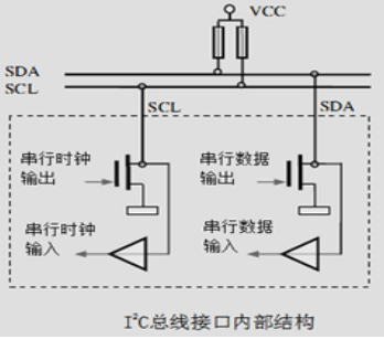
The physical layer of I2C bus consists of two lines: serial clock line SCL and serial data line SDA. Because these two lines are open drain output structures, they must be connected to the pull-up resistance to the high level. Therefore, when the bus is in the idle state, both lines are in the high level state. The following figure is the physical layer diagram of I2C bus.

I2C bus is very simple in physical connection. It is composed of SDA (serial data line), SCL (serial clock line) and pull-up resistor respectively. The communication principle is to control the high and low level timing of SCL and SDA lines to generate the signals required by I2C bus protocol for data transmission. When the bus is idle, the two wires are generally pulled high by the pull-up resistance connected above to maintain a high level.
I2C communication mode is half duplex, with only one SDA line. At the same time, it can only communicate in one direction, 485 is also half duplex, and SPI and uart are duplex.
2.2 protocol layer
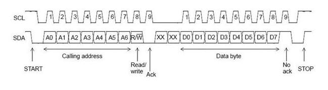
Each device on the I2C bus can be used as a master or slave device, and each device will correspond to a unique device address. Usually, we use the CPU module as the master device and other devices connected to the bus as the slave device. Bidirectional data transmission is carried out between master equipment and slave equipment on I2C bus in units of 8 bytes, and each unit must be followed by an ACK bit. The data is placed on the SDA data line when SCL is at low level, and the data is sampled when SCL is at high level. The following figure is the sequence diagram of data transmission protocol of I2C bus.

As can be seen from the figure, the transmission sequence of I2C bus includes: start condition, address frame, data frame, stop condition and repeat start condition.
Start condition: mark the official start of transmission. When SCL is at high level, SDA changes from high level to low level. In this way, all Slave devices will know that the transmission has started.
Address frame: the address frame always appears at the beginning of a communication, usually including 7-bit device address (MSB) and the last 1-bit read-write control bit (1 indicates read and 0 indicates write). Next comes the 1-bit NACK/ACK. After the 8-bit address is sent, the Slave device obtains the control right of the SDA. At this time, the Slave device should reply a * * ack (pull the SDA down) * * before the 9th clock pulse to indicate that the data reception is normal, otherwise it indicates that the data reception fails, and the control right is handed over to the Master device for processing.
Data frame: after the address frame is sent, the data can be transmitted. Each data frame has 8 bits, and the number of data frames can be arbitrary until a stop condition is generated. After each 8-bit data transmission is completed, the receiver needs to reply to an ACK/NACK.
Stop condition: when all data transmission is completed, when SCL is at high level, SDA changes from low level to high level. In addition to the start and stop conditions, during normal data transmission, when SCL is at high level, the value on SDA cannot change, otherwise stop conditions will be generated accidentally.

Repeat start condition: sometimes the Master device needs to exchange messages multiple times in one communication (such as switching read-write operations, etc.) and does not want interference from other Master devices. At this time, the repeat start condition can be used. In another communication, the Master device can generate multiple start conditions to complete multiple information exchanges, and finally generate a stop condition to end the whole communication process.
Response signal
After the master device sends 8bit data, it waits for the ack of the slave device, that is, in the 9th clk, it is valid to read the SDA low level; The master device pulls the clk low and changes the SDA to the input mode (pull-up resistance, default high level) to read bit 9. The clk is pulled high again to read the ACK sent from the slave device. There are two situations:
1. Write operation: the master device pulls up the clk and waits for the ACK to be read. After the slave device finds that the clk is pulled up, it pulls down the sda and tells the master device that the 8-bit data has been successfully received.
2. Read operation: the master device sends the chip address and register address, and the ack of these two bytes is pulled down by the slave device, which is the same as the write operation; The slave device starts sending data to the slave device. When the clk is low, the sda changes. When the master device clk is high, the sda is read, and the ACK is low by the master device; After the slave device sends a byte, the master device forces the ack to be raised and notifies the slave device not to send it again. When the slave device finds that the ACK has not been lowered, it considers that the master device has received an error and ends the transmission. Of course, the slave device itself knows that this is a byte.
3. Two ways of I2C - hardware I2C and software I2C
3.1 hardware I2C
The hardware I2C corresponds to the I2C peripherals on the chip, and there is a corresponding I2C driving circuit. The I2C pin used is also special, so the efficiency is much higher than that of the I2C simulated by software; It is generally stable, but the procedure is cumbersome. Hardware (Firmware) I2C is configured by directly calling internal registers; The software I2C does not have the concept of register.
Use of hardware I2C
As long as the corresponding registers are configured, the peripherals will generate the timing of standard serial port protocol. After initializing the I2C peripheral, you only need to set a register to position 1. At this time, the peripheral will control the corresponding SCL and SDA lines to automatically generate the I2C start signal, and the core does not need to directly control the level of the pin.
3.2 software I2C
Software I2C generally uses GPIO pins to control SCL and SDA lines to output high and low levels and simulate the timing of I2C protocol.
Use of software I2C
When controlling the generation of I2C start signal, control the GPIO pin as SCL line to output high level, then control the GPIO pin as SDA line to complete the switching from high level to low level during this period, and finally control the SCL line to switch to low level, so as to output a standard I2C start signal.
3.3 difference between the two
Hardware I2C directly uses peripherals to control pins, which can reduce the burden of CPU. However, when using hardware I2C, some fixed pins must be used as SCL and SDA, while software analog I2C can use any GPIO pin, which is relatively flexible. The usage of hardware I2C is more complex, and the flow of software I2C is clearer. If you want to understand I2C protocol in detail, you may better understand this process by using software I2C. In the process of using I2C, hardware I2C communication may be faster and more stable.
2, AHT20 temperature and humidity sensor
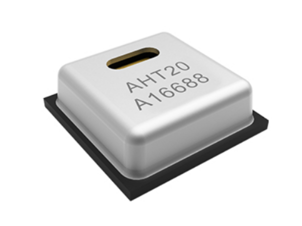
1. Appearance
2. Schematic diagram

3. Pin description
6 pins, name and function are as follows;
NC remains airborne
vdd is the input terminal of external power supply
GND ground
SCL I2C communication mode clock signal, bidirectional
SDA I2C communication mode data signal, bidirectional
NC remains airborne
4. Temperature and humidity measurement range

5. Advantages
- High precision, fully calibrated
- Extremely high reliability and excellent long-term stability (greatly improved compared with the previous generation aht10)
- Strong anti-interference ability
- High cost performance
- Suitable for harsh environmental conditions
3, Realization of AHT20 acquisition program
1. Subject requirements
Learn the I2C bus communication protocol, use STM32F103 to complete the data acquisition of AHT20 temperature and humidity sensor based on I2C protocol, and output the collected temperature humidity value through serial port. Specific tasks:
1) Explain what is "software I2C" and "hardware I2C"? (read Chapter 23 "I2C – reading and writing EEPROM" principle of wildfire supporting textbook)
2) Read AHT20 data manual and realize programming: collect temperature and humidity data every 2 seconds and send it to the upper computer (win10) through serial port.
2. Write code
In the sample code provided by wildfire, open an empty project that contains only the firmware library. Add relevant codes to the project:
The main function code is as follows:
main.c:
#include "delay.h"
#include "usart.h"
#include "bsp_i2c.h"


int main(void)
{
	delay_init();     //Delay Functions
	uart_init(115200);	 //uart function sets the baud rate to 115200
	IIC_Init();
		while(1)
	{
		printf("Temperature and humidity display");
		read_AHT20_once();
		delay_ms(2000);
  }
}
As shown in the main function, we call the delay.h delay function, usart.h universal synchronous / asynchronous serial receive / send function, call two functions in the main function body, circulate the "temperature and humidity display" in the while loop body, then read the AHT20 sensor once, then delay 2000ms is 2s, so the key point here is the content of AHT20. We'll explain next.
Then put the following functions in the same directory file of main function:
usart.c:
#include "sys.h"
#include "usart.h"


//STM32F103o?D?°?ày3ì
//?aoˉêy°?±?ày3ì
/********** mcudev.taobao.com 3??·  ********/


//
//è?1?ê1ó?ucos,?ò°üà¨????μ?í·???t?′?é.
#if SYSTEM_SUPPORT_UCOS
#include "includes.h"					//ucos ê1ó?
#endif
//
//STM32?a·¢°?
//′??ú13?ê??ˉ

//


//
//?óè?ò???′ú??,?§3?printfoˉêy,??2?Dèòa????use MicroLIB
#if 1
#pragma import(__use_no_semihosting)
//±ê×??aDèòaμ??§3?oˉêy
struct __FILE
{
	int handle;

};

FILE __stdout;
//?¨ò?_sys_exit()ò?±ü?aê1ó?°??÷?ú?£ê?
void _sys_exit(int x)
{
	x = x;
}
//???¨ò?fputcoˉêy
int fputc(int ch, FILE *f)
{
	while((USART1->SR&0X40)==0);//?-?··¢?í,?±μ?·¢?ííê±?
    USART1->DR = (u8) ch;
	return ch;
}
#endif

/*ê1ó?microLibμ?·?·¨*/
 /*
int fputc(int ch, FILE *f)
{
	USART_SendData(USART1, (uint8_t) ch);

	while (USART_GetFlagStatus(USART1, USART_FLAG_TC) == RESET) {}

    return ch;
}
int GetKey (void)  {

    while (!(USART1->SR & USART_FLAG_RXNE));

    return ((int)(USART1->DR & 0x1FF));
}
*/

#if EN_USART1_RX   //è?1?ê1?üá??óê?
//′??ú1?D??·t??3ìDò
//×¢òa,?áè?USARTx->SR?ü±ü?a?a??????μ?′í?ó
u8 USART_RX_BUF[USART_REC_LEN];     //?óê??o3?,×?′óUSART_REC_LEN??×??ú.
//?óê?×′ì?
//bit15£?	?óê?íê3é±ê??
//bit14£?	?óê?μ?0x0d
//bit13~0£?	?óê?μ?μ?óDD§×??úêy??
u16 USART_RX_STA=0;       //?óê?×′ì?±ê??

void uart_init(u32 bound){
    //GPIO???úéè??
  GPIO_InitTypeDef GPIO_InitStructure;
	USART_InitTypeDef USART_InitStructure;
	NVIC_InitTypeDef NVIC_InitStructure;

	RCC_APB2PeriphClockCmd(RCC_APB2Periph_USART1|RCC_APB2Periph_GPIOA, ENABLE);	//ê1?üUSART1£?GPIOAê±?ó
     //USART1_TX   PA.9
    GPIO_InitStructure.GPIO_Pin = GPIO_Pin_9; //PA.9
    GPIO_InitStructure.GPIO_Speed = GPIO_Speed_50MHz;
    GPIO_InitStructure.GPIO_Mode = GPIO_Mode_AF_PP;	//?′ó?í?íìê?3?
    GPIO_Init(GPIOA, &GPIO_InitStructure);

    //USART1_RX	  PA.10
    GPIO_InitStructure.GPIO_Pin = GPIO_Pin_10;
    GPIO_InitStructure.GPIO_Mode = GPIO_Mode_IN_FLOATING;//????ê?è?
    GPIO_Init(GPIOA, &GPIO_InitStructure);

   //Usart1 NVIC ????

    NVIC_InitStructure.NVIC_IRQChannel = USART1_IRQn;
	NVIC_InitStructure.NVIC_IRQChannelPreemptionPriority=3 ;//?à??ó??è??3
	NVIC_InitStructure.NVIC_IRQChannelSubPriority = 3;		//×óó??è??3
	NVIC_InitStructure.NVIC_IRQChannelCmd = ENABLE;			//IRQí¨μàê1?ü
	NVIC_Init(&NVIC_InitStructure);	//?ù?Y???¨μ?2?êy3?ê??ˉVIC??′??÷

   //USART 3?ê??ˉéè??

	USART_InitStructure.USART_BaudRate = bound;//ò?°?éè???a9600;
	USART_InitStructure.USART_WordLength = USART_WordLength_8b;//×?3¤?a8??êy?Y??ê?
	USART_InitStructure.USART_StopBits = USART_StopBits_1;//ò???í£?1??
	USART_InitStructure.USART_Parity = USART_Parity_No;//?T????D£?é??
	USART_InitStructure.USART_HardwareFlowControl = USART_HardwareFlowControl_None;//?Tó2?têy?Yá÷????
	USART_InitStructure.USART_Mode = USART_Mode_Rx | USART_Mode_Tx;	//ê?·¢?£ê?

    USART_Init(USART1, &USART_InitStructure); //3?ê??ˉ′??ú
    USART_ITConfig(USART1, USART_IT_RXNE, ENABLE);//?a???D??
    USART_Cmd(USART1, ENABLE);                    //ê1?ü′??ú

}


void USART1_IRQHandler(void)                	//′??ú1?D??·t??3ìDò
	{
	u8 Res;
#ifdef OS_TICKS_PER_SEC	 	//è?1?ê±?ó?ú??êy?¨ò?á?,?μ?÷òaê1ó?ucosIIá?.
	OSIntEnter();
#endif
	if(USART_GetITStatus(USART1, USART_IT_RXNE) != RESET)  //?óê??D??(?óê?μ?μ?êy?Y±?D?ê?0x0d 0x0a?á?2)
		{
		Res =USART_ReceiveData(USART1);//(USART1->DR);	//?áè??óê?μ?μ?êy?Y

		if((USART_RX_STA&0x8000)==0)//?óê??′íê3é
			{
			if(USART_RX_STA&0x4000)//?óê?μ?á?0x0d
				{
				if(Res!=0x0a)USART_RX_STA=0;//?óê?′í?ó,??D??aê?
				else USART_RX_STA|=0x8000;	//?óê?íê3éá?
				}
			else //?1??ê?μ?0X0D
				{
				if(Res==0x0d)USART_RX_STA|=0x4000;
				else
					{
					USART_RX_BUF[USART_RX_STA&0X3FFF]=Res ;
					USART_RX_STA++;
					if(USART_RX_STA>(USART_REC_LEN-1))USART_RX_STA=0;//?óê?êy?Y′í?ó,??D??aê??óê?
					}
				}
			}
     }
#ifdef OS_TICKS_PER_SEC	 	//è?1?ê±?ó?ú??êy?¨ò?á?,?μ?÷òaê1ó?ucosIIá?.
	OSIntExit();
#endif
}
#endif
We see that usart.h and sys.h files are called here, so we need to write these two codes next:
usart.h:
#ifndef __USART_H
#define __USART_H
#include "stdio.h"
#include "sys.h"

//STM32F103o?D?°?ày3ì
//?aoˉêy°?±?ày3ì
/********** mcudev.taobao.com 3??·  ********/

//
//STM32?a·¢°?
//′??ú13?ê??ˉ

#define USART_REC_LEN  			200  	//?¨ò?×?′ó?óê?×??úêy 200
#define EN_USART1_RX 			1		    //ê1?ü£¨1£?/???1£¨0£?′??ú1?óê?

extern u8  USART_RX_BUF[USART_REC_LEN]; //?óê??o3?,×?′óUSART_REC_LEN??×??ú.??×??ú?a??DD·?
extern u16 USART_RX_STA;         		//?óê?×′ì?±ê??
//è?1???′??ú?D???óê?£???2?òa×¢êíò???oê?¨ò?
void uart_init(u32 bound);
#endif
sys.c:
#include "sys.h"


//STM32F103o?D?°?ày3ì
//?aoˉêy°?±?ày3ì
/********** mcudev.taobao.com 3??·  ********/

//

//STM32?a·¢°?
//?μí3?D??·?×ééè???ˉ

//********************************************************************************
void NVIC_Configuration(void)
{

    NVIC_PriorityGroupConfig(NVIC_PriorityGroup_2);	//éè??NVIC?D??·?×é2:2???à??ó??è??£?2???ìó|ó??è??

}
sys.h:
#ifndef __SYS_H
#define __SYS_H
#include "stm32f10x.h"
//


//STM32F103o?D?°?ày3ì
//?aoˉêy°?±?ày3ì
/********** mcudev.taobao.com 3??·  ********/


//

//0,2??§3?ucos
//1,?§3?ucos
#define SYSTEM_SUPPORT_UCOS		0		//?¨ò??μí3???t?Dê?·??§3?UCOS


//??′?2ù×÷,êμ??51àà??μ?GPIO????1|?ü
//??ì?êμ??????,2???<<CM3è¨ít????>>μú????(87ò3~92ò3).
//IO?ú2ù×÷oê?¨ò?
#define BITBAND(addr, bitnum) ((addr & 0xF0000000)+0x2000000+((addr &0xFFFFF)<<5)+(bitnum<<2))
#define MEM_ADDR(addr)  *((volatile unsigned long  *)(addr))
#define BIT_ADDR(addr, bitnum)   MEM_ADDR(BITBAND(addr, bitnum))
//IO?úμ??·ó3é?
#define GPIOA_ODR_Addr    (GPIOA_BASE+12) //0x4001080C
#define GPIOB_ODR_Addr    (GPIOB_BASE+12) //0x40010C0C
#define GPIOC_ODR_Addr    (GPIOC_BASE+12) //0x4001100C
#define GPIOD_ODR_Addr    (GPIOD_BASE+12) //0x4001140C
#define GPIOE_ODR_Addr    (GPIOE_BASE+12) //0x4001180C
#define GPIOF_ODR_Addr    (GPIOF_BASE+12) //0x40011A0C
#define GPIOG_ODR_Addr    (GPIOG_BASE+12) //0x40011E0C

#define GPIOA_IDR_Addr    (GPIOA_BASE+8) //0x40010808
#define GPIOB_IDR_Addr    (GPIOB_BASE+8) //0x40010C08
#define GPIOC_IDR_Addr    (GPIOC_BASE+8) //0x40011008
#define GPIOD_IDR_Addr    (GPIOD_BASE+8) //0x40011408
#define GPIOE_IDR_Addr    (GPIOE_BASE+8) //0x40011808
#define GPIOF_IDR_Addr    (GPIOF_BASE+8) //0x40011A08
#define GPIOG_IDR_Addr    (GPIOG_BASE+8) //0x40011E08

//IO?ú2ù×÷,????μ¥ò?μ?IO?ú!
//è·±£nμ??μD?óú16!
#define PAout(n)   BIT_ADDR(GPIOA_ODR_Addr,n)  //ê?3?
#define PAin(n)    BIT_ADDR(GPIOA_IDR_Addr,n)  //ê?è?

#define PBout(n)   BIT_ADDR(GPIOB_ODR_Addr,n)  //ê?3?
#define PBin(n)    BIT_ADDR(GPIOB_IDR_Addr,n)  //ê?è?

#define PCout(n)   BIT_ADDR(GPIOC_ODR_Addr,n)  //ê?3?
#define PCin(n)    BIT_ADDR(GPIOC_IDR_Addr,n)  //ê?è?

#define PDout(n)   BIT_ADDR(GPIOD_ODR_Addr,n)  //ê?3?
#define PDin(n)    BIT_ADDR(GPIOD_IDR_Addr,n)  //ê?è?

#define PEout(n)   BIT_ADDR(GPIOE_ODR_Addr,n)  //ê?3?
#define PEin(n)    BIT_ADDR(GPIOE_IDR_Addr,n)  //ê?è?

#define PFout(n)   BIT_ADDR(GPIOF_ODR_Addr,n)  //ê?3?
#define PFin(n)    BIT_ADDR(GPIOF_IDR_Addr,n)  //ê?è?

#define PGout(n)   BIT_ADDR(GPIOG_ODR_Addr,n)  //ê?3?
#define PGin(n)    BIT_ADDR(GPIOG_IDR_Addr,n)  //ê?è?


void NVIC_Configuration(void);


#endif
bsp_i2c.c:
#include "bsp_i2c.h"
#include "delay.h"
uint8_t ack_status=0;
uint8_t readByte[6];
uint8_t AHT20_status=0;
uint32_t H1=0; //Humility
uint32_t T1=0; //Temperature
uint8_t AHT20_OutData[4];
uint8_t AHT20sendOutData[10] = {0xFA, 0x06, 0x0A, 0x00, 0x00, 0x00, 0x00, 0x00, 0x00, 0xFF};
void IIC_Init(void)
{
GPIO_InitTypeDef GPIO_InitStructure;
RCC_APB2PeriphClockCmd( RCC_APB2Periph_GPIOB, ENABLE );
GPIO_InitStructure.GPIO_Pin = GPIO_Pin_6|GPIO_Pin_7;
GPIO_InitStructure.GPIO_Mode = GPIO_Mode_Out_PP ; //í?íìê?3?
GPIO_InitStructure.GPIO_Speed = GPIO_Speed_50MHz;
GPIO_Init(GPIOB, &GPIO_InitStructure);
IIC_SCL=1;
IIC_SDA=1;
}
//2úéúIIC?eê?D?o?
void IIC_Start(void)
{
SDA_OUT(); //sda??ê?3?
IIC_SDA=1;
IIC_SCL=1;
delay_us(4);
IIC_SDA=0;//START:when CLK is high,DATA change form high to low
delay_us(4);
IIC_SCL=0;//?ˉ×?I2C×ü??£?×?±?·¢?í?ò?óê?êy?Y
}
//2úéúIICí£?1D?o?
void IIC_Stop(void)
{
SDA_OUT();//sda??ê?3?
IIC_SCL=0;
IIC_SDA=0;//STOP:when CLK is high DATA change form low to high
delay_us(4);
IIC_SCL=1;
IIC_SDA=1;//·¢?íI2C×ü???áê?D?o?
delay_us(4);
}
//μè′yó|′eD?o?μ?à′
//·μ???μ£o1£??óê?ó|′e꧰ü
// 0£??óê?ó|′e3é1|
u8 IIC_Wait_Ack(void)
{
u8 ucErrTime=0;
SDA_IN(); //SDAéè???aê?è?
IIC_SDA=1;delay_us(1);
IIC_SCL=1;delay_us(1);
while(READ_SDA)
{
ucErrTime++;
if(ucErrTime>250)
{
IIC_Stop();
return 1;
}
}
IIC_SCL=0;//ê±?óê?3?0
return 0;
}
//2úéúACKó|′e
void IIC_Ack(void)
{
IIC_SCL=0;
SDA_OUT();
IIC_SDA=0;
delay_us(2);
IIC_SCL=1;
delay_us(2);
IIC_SCL=0;
}
//2?2úéúACKó|′e
void IIC_NAck(void)
{
IIC_SCL=0;
SDA_OUT();
IIC_SDA=1;
delay_us(2);
IIC_SCL=1;
delay_us(2);
IIC_SCL=0;
}
//IIC·¢?íò???×??ú
//·μ??′ó?úóD?Tó|′e
//1£?óDó|′e
//0£??Tó|′e
void IIC_Send_Byte(u8 txd)
{
u8 t;
SDA_OUT();
IIC_SCL=0;//à-μíê±?ó?aê?êy?Y′?ê?
for(t=0;t<8;t++)
{
IIC_SDA=(txd&0x80)>>7;
txd<<=1;
delay_us(2); //??TEA5767?aèy???óê±??ê?±?D?μ?
IIC_SCL=1;
delay_us(2);
IIC_SCL=0;
delay_us(2);
}
}
//?á1??×??ú£?ack=1ê±£?·¢?íACK£?ack=0£?·¢?ínACK
u8 IIC_Read_Byte(unsigned char ack)
{
unsigned char i,receive=0;
SDA_IN();//SDAéè???aê?è?
for(i=0;i<8;i++ )
{
IIC_SCL=0;
delay_us(2);
IIC_SCL=1;
receive<<=1;
if(READ_SDA)receive++;
delay_us(1);
}
if (!ack)
IIC_NAck();//·¢?ínACK
else
IIC_Ack(); //·¢?íACK
return receive;
}
void IIC_WriteByte(uint16_t addr,uint8_t data,uint8_t device_addr)
{
IIC_Start();
if(device_addr==0xA0) //eepromμ??·′óóú1×??ú
IIC_Send_Byte(0xA0 + ((addr/256)<<1));//·¢?í??μ??·
else
IIC_Send_Byte(device_addr); //·¢?÷?tμ??·
IIC_Wait_Ack();
IIC_Send_Byte(addr&0xFF); //·¢?íμíμ??·
IIC_Wait_Ack();
IIC_Send_Byte(data); //·¢?í×??ú
IIC_Wait_Ack();
IIC_Stop();//2úéúò???í£?1ì??t
if(device_addr==0xA0) //
delay_ms(10);
else
delay_us(2);
}
uint16_t IIC_ReadByte(uint16_t addr,uint8_t device_addr,uint8_t ByteNumToRead) //?á??′??÷?ò?áêy?Y
{
uint16_t data;
IIC_Start();
if(device_addr==0xA0)
IIC_Send_Byte(0xA0 + ((addr/256)<<1));
else
IIC_Send_Byte(device_addr);
IIC_Wait_Ack();
IIC_Send_Byte(addr&0xFF); //·¢?íμíμ??·
IIC_Wait_Ack();
IIC_Start();
IIC_Send_Byte(device_addr+1); //·¢?÷?tμ??·
IIC_Wait_Ack();
if(ByteNumToRead == 1)//LM75???èêy?Y?a11bit
{
data=IIC_Read_Byte(0);
}
else
{
data=IIC_Read_Byte(1);
data=(data<<8)+IIC_Read_Byte(0);
}
IIC_Stop();//2úéúò???í£?1ì??t
return data;
}
/**********
*é???2?·??aIO?ú?£?éI2C????
*
*′ó?aò????aê??aAHT20μ?????I2C
*oˉêy??óDIICoíI2Cμ???±e£???×¢òa£?£?£?£?£?
*
*2020/2/23×?oóDT??è??ú
*
***********/
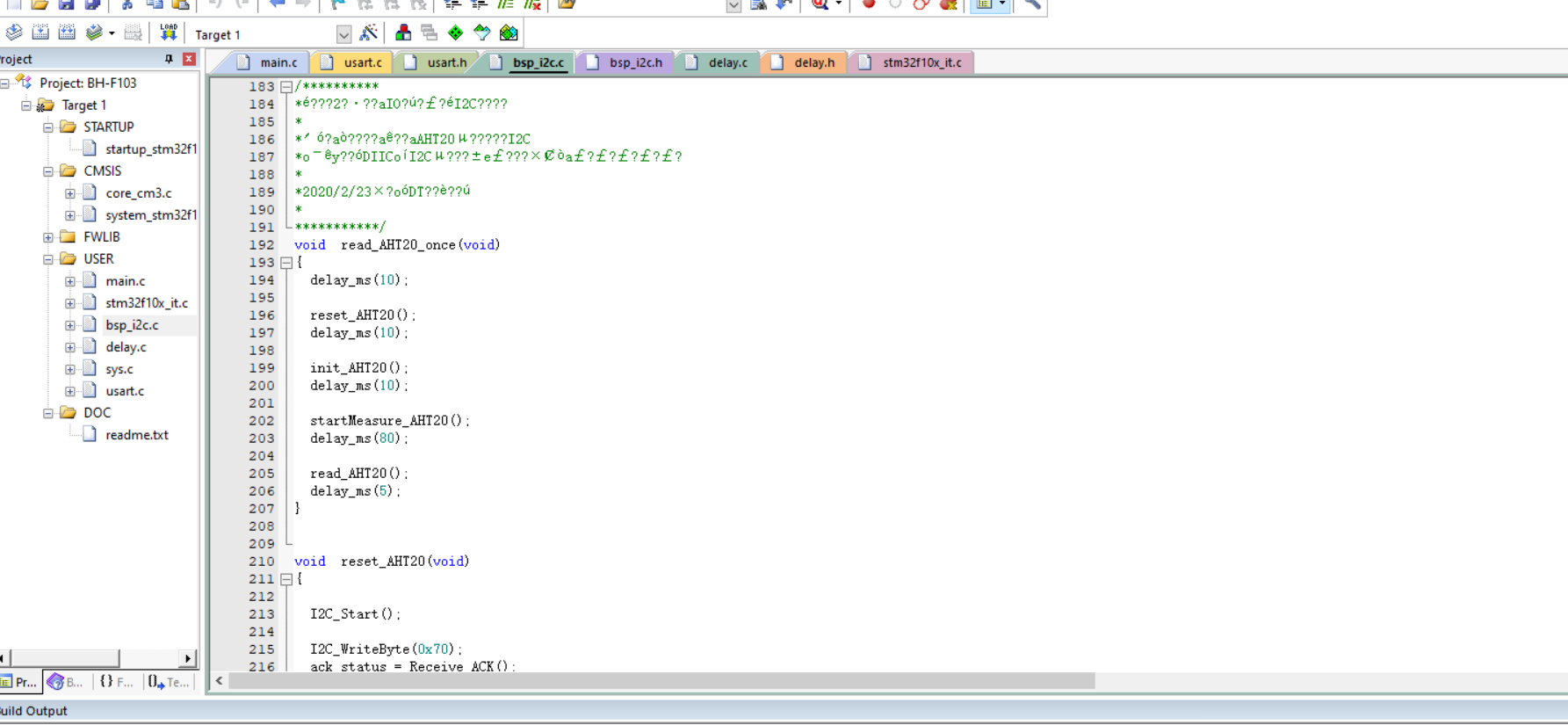
void read_AHT20_once(void)
{
delay_ms(10);
reset_AHT20();
delay_ms(10);
init_AHT20();
delay_ms(10);
startMeasure_AHT20();
delay_ms(80);
read_AHT20();
delay_ms(5);
}
void reset_AHT20(void)
{
I2C_Start();
I2C_WriteByte(0x70);
ack_status = Receive_ACK();
if(ack_status) printf("1");
else printf("1-n-");
I2C_WriteByte(0xBA);
ack_status = Receive_ACK();
if(ack_status) printf("2");
else printf("2-n-");
I2C_Stop();
/*
AHT20_OutData[0] = 0;
AHT20_OutData[1] = 0;
AHT20_OutData[2] = 0;
AHT20_OutData[3] = 0;
*/
}
void init_AHT20(void)
{
I2C_Start();
I2C_WriteByte(0x70);
ack_status = Receive_ACK();
if(ack_status) printf("3");
else printf("3-n-");
I2C_WriteByte(0xE1);
ack_status = Receive_ACK();
if(ack_status) printf("4");
else printf("4-n-");
I2C_WriteByte(0x08);
ack_status = Receive_ACK();
if(ack_status) printf("5");
else printf("5-n-");
I2C_WriteByte(0x00);
ack_status = Receive_ACK();
if(ack_status) printf("6");
else printf("6-n-");
I2C_Stop();
}
void startMeasure_AHT20(void)
{
//------------
I2C_Start();
I2C_WriteByte(0x70);
ack_status = Receive_ACK();
if(ack_status) printf("7");
else printf("7-n-");
I2C_WriteByte(0xAC);
ack_status = Receive_ACK();
if(ack_status) printf("8");
else printf("8-n-");
I2C_WriteByte(0x33);
ack_status = Receive_ACK();
if(ack_status) printf("9");
else printf("9-n-");
I2C_WriteByte(0x00);
ack_status = Receive_ACK();
if(ack_status) printf("10");
else printf("10-n-");
I2C_Stop();
}
void read_AHT20(void)
{
uint8_t i;
for(i=0; i<6; i++)
{
readByte[i]=0;
}
//-------------
I2C_Start();
I2C_WriteByte(0x71);
ack_status = Receive_ACK();
readByte[0]= I2C_ReadByte();
Send_ACK();
readByte[1]= I2C_ReadByte();
Send_ACK();
readByte[2]= I2C_ReadByte();
Send_ACK();
readByte[3]= I2C_ReadByte();
Send_ACK();
readByte[4]= I2C_ReadByte();
Send_ACK();
readByte[5]= I2C_ReadByte();
SendNot_Ack();
//Send_ACK();
I2C_Stop();
//--------------
if( (readByte[0] & 0x68) == 0x08 )
{
H1 = readByte[1];
H1 = (H1<<8) | readByte[2];
H1 = (H1<<8) | readByte[3];
H1 = H1>>4;
H1 = (H1*1000)/1024/1024;
T1 = readByte[3];
T1 = T1 & 0x0000000F;
T1 = (T1<<8) | readByte[4];
T1 = (T1<<8) | readByte[5];
T1 = (T1*2000)/1024/1024 - 500;
AHT20_OutData[0] = (H1>>8) & 0x000000FF;
AHT20_OutData[1] = H1 & 0x000000FF;
AHT20_OutData[2] = (T1>>8) & 0x000000FF;
AHT20_OutData[3] = T1 & 0x000000FF;
}
else
{
AHT20_OutData[0] = 0xFF;
AHT20_OutData[1] = 0xFF;
AHT20_OutData[2] = 0xFF;
AHT20_OutData[3] = 0xFF;
printf("lyy");
}
printf("\r\n");
printf("temperature:%d%d.%d",T1/100,(T1/10)%10,T1%10);
printf("humidity:%d%d.%d",H1/100,(H1/10)%10,H1%10);
printf("\r\n");
}
uint8_t Receive_ACK(void)
{
uint8_t result=0;
uint8_t cnt=0;
IIC_SCL = 0;
SDA_IN();
delay_us(4);
IIC_SCL = 1;
delay_us(4);
while(READ_SDA && (cnt<100))
{
cnt++;
}
IIC_SCL = 0;
delay_us(4);
if(cnt<100)
{
result=1;
}
return result;
}
void Send_ACK(void)
{
SDA_OUT();
IIC_SCL = 0;
delay_us(4);
IIC_SDA = 0;
delay_us(4);
IIC_SCL = 1;
delay_us(4);
IIC_SCL = 0;
delay_us(4);
SDA_IN();
}
void SendNot_Ack(void)
{
SDA_OUT();
IIC_SCL = 0;
delay_us(4);
IIC_SDA = 1;
delay_us(4);
IIC_SCL = 1;
delay_us(4);
IIC_SCL = 0;
delay_us(4);
IIC_SDA = 0;
delay_us(4);
}
void I2C_WriteByte(uint8_t input)
{
uint8_t i;
SDA_OUT();
for(i=0; i<8; i++)
{
IIC_SCL = 0;
delay_ms(5);
if(input & 0x80)
{
IIC_SDA = 1;
//delaymm(10);
}
else
{
IIC_SDA = 0;
//delaymm(10);
}
IIC_SCL = 1;
delay_ms(5);
input = (input<<1);
}
IIC_SCL = 0;
delay_us(4);
SDA_IN();
delay_us(4);
}
uint8_t I2C_ReadByte(void)
{
uint8_t resultByte=0;
uint8_t i=0, a=0;
IIC_SCL = 0;
SDA_IN();
delay_ms(4);
for(i=0; i<8; i++)
{
IIC_SCL = 1;
delay_ms(3);
a=0;
if(READ_SDA)
{
a=1;
}
else
{
a=0;
}
//resultByte = resultByte | a;
resultByte = (resultByte << 1) | a;
IIC_SCL = 0;
delay_ms(3);
}
SDA_IN();
delay_ms(10);
return resultByte;
}
void set_AHT20sendOutData(void)
{
/* --------------------------
* 0xFA 0x06 0x0A temperature(2 Bytes) humility(2Bytes) short Address(2 Bytes)
* And Check (1 byte)
* -------------------------*/
AHT20sendOutData[3] = AHT20_OutData[0];
AHT20sendOutData[4] = AHT20_OutData[1];
AHT20sendOutData[5] = AHT20_OutData[2];
AHT20sendOutData[6] = AHT20_OutData[3];
// AHT20sendOutData[7] = (drf1609.shortAddress >> 8) & 0x00FF;
// AHT20sendOutData[8] = drf1609.shortAddress & 0x00FF;
// AHT20sendOutData[9] = getXY(AHT20sendOutData,10);
}
void I2C_Start(void)
{
SDA_OUT();
IIC_SCL = 1;
delay_ms(4);
IIC_SDA = 1;
delay_ms(4);
IIC_SDA = 0;
delay_ms(4);
IIC_SCL = 0;
delay_ms(4);
}
void I2C_Stop(void)
{
SDA_OUT();
IIC_SDA = 0;
delay_ms(4);
IIC_SCL = 1;
delay_ms(4);
IIC_SDA = 1;
delay_ms(4);
}
bsp_i2c.h:
#ifndef __BSP_I2C_H
#define __BSP_I2C_H

#include "sys.h"
#include "delay.h"
#include "usart.h"
//ê1ó?IIC1 1ò??M24C02,OLED,LM75AD,HT1382    PB6,PB7

#define SDA_IN()  {GPIOB->CRL&=0X0FFFFFFF;GPIOB->CRL|=(u32)8<<28;}
#define SDA_OUT() {GPIOB->CRL&=0X0FFFFFFF;GPIOB->CRL|=(u32)3<<28;}

//IO2ù×÷oˉêy
#define IIC_SCL    PBout(6) //SCL
#define IIC_SDA    PBout(7) //SDA
#define READ_SDA   PBin(7)  //ê?è?SDA


//IIC?ùóD2ù×÷oˉêy
void IIC_Init(void);                //3?ê??ˉIICμ?IO?ú
void IIC_Start(void);				//·¢?íIIC?aê?D?o?
void IIC_Stop(void);	  			//·¢?íIICí£?1D?o?
void IIC_Send_Byte(u8 txd);			//IIC·¢?íò???×??ú
u8 IIC_Read_Byte(unsigned char ack);//IIC?áè?ò???×??ú
u8 IIC_Wait_Ack(void); 				//IICμè′yACKD?o?
void IIC_Ack(void);					//IIC·¢?íACKD?o?
void IIC_NAck(void);				//IIC2?·¢?íACKD?o?

void IIC_WriteByte(uint16_t addr,uint8_t data,uint8_t device_addr);
uint16_t IIC_ReadByte(uint16_t addr,uint8_t device_addr,uint8_t ByteNumToRead);//??′??÷μ??·£??÷?tμ??·£?òa?áμ?×??úêy


void  read_AHT20_once(void);
void  reset_AHT20(void);
void  init_AHT20(void);
void  startMeasure_AHT20(void);
void  read_AHT20(void);
uint8_t  Receive_ACK(void);
void  Send_ACK(void);
void  SendNot_Ack(void);
void I2C_WriteByte(uint8_t  input);
uint8_t I2C_ReadByte(void);
void  set_AHT20sendOutData(void);
void  I2C_Start(void);
void  I2C_Stop(void);
#endif
Delay function:
delay.c:
#include "delay.h"
#include "sys.h"

//STM32F103o?D?°?ày3ì
//?aoˉêy°?±?ày3ì
/********** mcudev.taobao.com 3??·  ********/


//
//è?1?ê1ó?ucos,?ò°üà¨????μ?í·???t?′?é.
#if SYSTEM_SUPPORT_UCOS
#include "includes.h"					//ucos ê1ó?
#endif
//

//STM32?a·¢°?
//ê1ó?SysTickμ???í¨??êy?£ê????ó3ù??DD1üàí
//°üà¨delay_us,delay_ms

//
static u8  fac_us=0;//us?óê±±?3?êy
static u16 fac_ms=0;//ms?óê±±?3?êy
#ifdef OS_CRITICAL_METHOD 	//è?1?OS_CRITICAL_METHOD?¨ò?á?,?μ?÷ê1ó?ucosIIá?.
//systick?D??·t??oˉêy,ê1ó?ucosê±ó?μ?
void SysTick_Handler(void)
{
	OSIntEnter();		//??è??D??
    OSTimeTick();       //μ÷ó?ucosμ?ê±?ó·t??3ìDò
    OSIntExit();        //′¥·¢è????D??èí?D??
}
#endif

//3?ê??ˉ?ó3ùoˉêy
//μ±ê1ó?ucosμ?ê±oò,′?oˉêy?á3?ê??ˉucosμ?ê±?ó?ú??
//SYSTICKμ?ê±?ó1ì?¨?aHCLKê±?óμ?1/8
//SYSCLK:?μí3ê±?ó
void delay_init()
{

#ifdef OS_CRITICAL_METHOD 	//è?1?OS_CRITICAL_METHOD?¨ò?á?,?μ?÷ê1ó?ucosIIá?.
	u32 reload;
#endif
	SysTick_CLKSourceConfig(SysTick_CLKSource_HCLK_Div8);	//????ía2?ê±?ó  HCLK/8
	fac_us=SystemCoreClock/8000000;	//?a?μí3ê±?óμ?1/8

#ifdef OS_CRITICAL_METHOD 	//è?1?OS_CRITICAL_METHOD?¨ò?á?,?μ?÷ê1ó?ucosIIá?.
	reload=SystemCoreClock/8000000;		//?????óμ???êy′?êy μ¥???aK
	reload*=1000000/OS_TICKS_PER_SEC;//?ù?YOS_TICKS_PER_SECéè?¨ò?3?ê±??
							//reload?a24????′??÷,×?′ó?μ:16777216,?ú72M??,??o?1.86s×óóò
	fac_ms=1000/OS_TICKS_PER_SEC;//′ú±íucos?éò??óê±μ?×?éùμ¥??
	SysTick->CTRL|=SysTick_CTRL_TICKINT_Msk;   	//?a??SYSTICK?D??
	SysTick->LOAD=reload; 	//??1/OS_TICKS_PER_SEC???D??ò?′?
	SysTick->CTRL|=SysTick_CTRL_ENABLE_Msk;   	//?a??SYSTICK
#else
	fac_ms=(u16)fac_us*1000;//·?ucos??,′ú±í????msDèòaμ?systickê±?óêy
#endif
}

#ifdef OS_CRITICAL_METHOD	//ê1ó?á?ucos
//?óê±nus
//nus?aòa?óê±μ?usêy.
void delay_us(u32 nus)
{
	u32 ticks;
	u32 told,tnow,tcnt=0;
	u32 reload=SysTick->LOAD;	//LOADμ??μ
	ticks=nus*fac_us; 			//Dèòaμ??ú??êy
	tcnt=0;
	told=SysTick->VAL;        	//????è?ê±μ???êy?÷?μ
	while(1)
	{
		tnow=SysTick->VAL;
		if(tnow!=told)
		{
			if(tnow<told)tcnt+=told-tnow;//?aà?×¢òaò???SYSTICKê?ò???μY??μ???êy?÷?í?éò?á?.
			else tcnt+=reload-tnow+told;
			told=tnow;
			if(tcnt>=ticks)break;//ê±??3?1y/μèóúòa?ó3ùμ?ê±??,?òí?3?.
		}
	};
}
//?óê±nms
//nms:òa?óê±μ?msêy
void delay_ms(u16 nms)
{
	if(OSRunning==TRUE)//è?1?osò??-?ú?üá?
	{
		if(nms>=fac_ms)//?óê±μ?ê±??′óóúucosμ?×?éùê±???ü?ú
		{
   			OSTimeDly(nms/fac_ms);//ucos?óê±
		}
		nms%=fac_ms;				//ucosò??-?T·¨ìá1??a?′D?μ??óê±á?,2éó???í¨·?ê??óê±
	}
	delay_us((u32)(nms*1000));	//??í¨·?ê??óê±,′?ê±ucos?T·¨???ˉμ÷?è.
}
#else//2?ó?ucosê±
//?óê±nus
//nus?aòa?óê±μ?usêy.
void delay_us(u32 nus)
{
	u32 temp;
	SysTick->LOAD=nus*fac_us; //ê±???ó??
	SysTick->VAL=0x00;        //??????êy?÷
	SysTick->CTRL|=SysTick_CTRL_ENABLE_Msk ;          //?aê?μ1êy
	do
	{
		temp=SysTick->CTRL;
	}
	while(temp&0x01&&!(temp&(1<<16)));//μè′yê±??μ?′?
	SysTick->CTRL&=~SysTick_CTRL_ENABLE_Msk;       //1?±???êy?÷
	SysTick->VAL =0X00;       //??????êy?÷
}
//?óê±nms
//×¢òanmsμ?·??§
//SysTick->LOAD?a24????′??÷,?ùò?,×?′ó?óê±?a:
//nms<=0xffffff*8*1000/SYSCLK
//SYSCLKμ¥???aHz,nmsμ¥???ams
//??72Mì??t??,nms<=1864
void delay_ms(u16 nms)
{
	u32 temp;
	SysTick->LOAD=(u32)nms*fac_ms;//ê±???ó??(SysTick->LOAD?a24bit)
	SysTick->VAL =0x00;           //??????êy?÷
	SysTick->CTRL|=SysTick_CTRL_ENABLE_Msk ;          //?aê?μ1êy
	do
	{
		temp=SysTick->CTRL;
	}
	while(temp&0x01&&!(temp&(1<<16)));//μè′yê±??μ?′?
	SysTick->CTRL&=~SysTick_CTRL_ENABLE_Msk;       //1?±???êy?÷
	SysTick->VAL =0X00;       //??????êy?÷
}
#endif
delay.h:
#ifndef __DELAY_H
#define __DELAY_H
#include "sys.h"
//

//STM32F103o?D?°?ày3ì
//?aoˉêy°?±?ày3ì
/********** mcudev.taobao.com 3??·  ********/


//ê1ó?SysTickμ???í¨??êy?£ê????ó3ù??DD1üàí
//°üà¨delay_us,delay_ms

//
void delay_init(void);
void delay_ms(u16 nms);
void delay_us(u32 nus);

#endif
In bsp_i2c.c function contains the preparation of sensor contents, mainly including sensor initialization and data reading and writing procedures:
initialization:
void  read_AHT20_once(void)
{
	delay_ms(10);

	reset_AHT20();//Reset AHT20 chip
	delay_ms(10);

	init_AHT20();//Initialize AHT20 chip
	delay_ms(10);

	startMeasure_AHT20();//Start testing AHT20 chip
	delay_ms(80);

	read_AHT20();//Read the data collected by AHT20
	delay_ms(5);
}
Read / write data:
void read_AHT20(void)
{
	uint8_t   i;

	for(i=0; i<6; i++)
	{
		readByte[i]=0;
	}

	//-------------
	I2C_Start();//I2C start

	I2C_WriteByte(0x71);//I2C write data
	ack_status = Receive_ACK();//Received response information
	readByte[0]= I2C_ReadByte();//I2C read data
	Send_ACK();//Send response information

	readByte[1]= I2C_ReadByte();
	Send_ACK();

	readByte[2]= I2C_ReadByte();
	Send_ACK();

	readByte[3]= I2C_ReadByte();
	Send_ACK();

	readByte[4]= I2C_ReadByte();
	Send_ACK();

	readByte[5]= I2C_ReadByte();
	SendNot_Ack();
	//Send_ACK();

	I2C_Stop();//I2C stop function

	//--------------
	if( (readByte[0] & 0x68) == 0x08 )
	{
		H1 = readByte[1];
		H1 = (H1<<8) | readByte[2];
		H1 = (H1<<8) | readByte[3];
		H1 = H1>>4;

		H1 = (H1*1000)/1024/1024;

		T1 = readByte[3];
		T1 = T1 & 0x0000000F;
		T1 = (T1<<8) | readByte[4];
		T1 = (T1<<8) | readByte[5];

		T1 = (T1*2000)/1024/1024 - 500;

		AHT20_OutData[0] = (H1>>8) & 0x000000FF;
		AHT20_OutData[1] = H1 & 0x000000FF;

		AHT20_OutData[2] = (T1>>8) & 0x000000FF;
		AHT20_OutData[3] = T1 & 0x000000FF;
	}
	else
	{
		AHT20_OutData[0] = 0xFF;
		AHT20_OutData[1] = 0xFF;

		AHT20_OutData[2] = 0xFF;
		AHT20_OutData[3] = 0xFF;
		printf("lyy");

	}
	printf("\r\n");
	//According to the calculation formula of temperature and humidity in AHT20 chip, the final result is obtained and displayed through serial port
	printf("temperature:%d%d.%d",T1/100,(T1/10)%10,T1%10);
	printf("humidity:%d%d.%d",H1/100,(H1/10)%10,H1%10);
	printf("\r\n");
}
3. Perform the test
First, add the code written above to the project file:
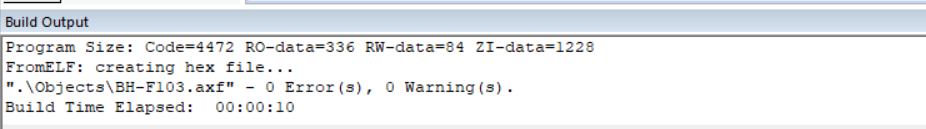
Compile execution check for errors:
4. Result display

It can be seen that the result display program successively reads the temperature and humidity information. When we breathe out into the sensor, we will find that the displayed temperature rises by two to three degrees, and the humidity rises greatly.
4, References
https://blog.csdn.net/xx_0305401/article/details/81914528
https://blog.csdn.net/weixin_40774605/article/details/88399276
https://blog.csdn.net/weixin_40877615/article/details/94338850