Some problems about stm32 driving matrix keyboard and alternative methods of matrix keyboard
About matrix keyboard
For general buttons, I generally prefer interrupt mode to trigger. One is to save the resources of single chip microcomputer without having to scan it back and forth. Second, the interrupt is very efficient and easy to handle. But for the matrix keyboard, I racked my brains and didn't come up with a way to realize it entirely through interruption. Let's introduce the pits I stepped on
Interrupt + status detection (PIT)
First, the figure above
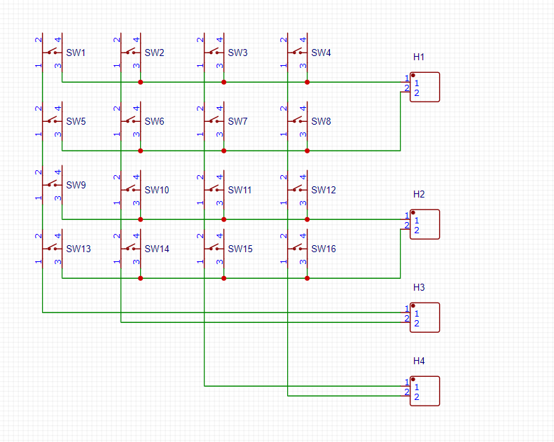
The above picture is drawn with Lichuang eda, which is messy because it uses microswitches. Look at the picture below
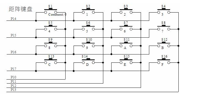
At this time, my method is to pull up the input of p14, p15, p16 and p17, set it as the external interrupt channel, and trigger the falling edge. P10,P11,P12,P13 input pull-down. At this time, it is assumed that if I press the button S1 and the level is pulled down, the P14 port interrupt will be triggered. In the interrupt, detect which port P10, P11, p12 and P13 has the level increased. Here is the P10 port, and it can be determined that the S1 key is pressed. But the ideal is plump and shows a sense of bone. Since the IO port is set with input pull-up and input pull-down, the pull-down resistance inside stm32 is 40K Ω. After pressing the key in this way, the level of the two IO ports connected to the key is about 1.6V. TTL level is used in stm32. If it is higher than 2V, it is high level, and if it is lower than 0.8V, it is low level. What do you call 1.6V.
If you want to use this method, you have to design a level conversion circuit, but a matrix keyboard is not worth it. Use another method.
So I want to change to external pull-up or pull-down, and all IO ports are set to floating input. But after reasoning, it is found that this is similar to which of the above methods, but it is nothing more than external pull-down. However, I can change the size of the external pull-up resistance to control the state level after pressing the button, but the problem occurs again. I can only meet one direction, that is, if I want to meet the interrupt conditions of the row, I will not be able to detect the level change at the column. If I can detect the level change at the column, my row will not be able to generate an interrupt.
So I want to set the row as push-pull output and keep cycling, but only one row of output is high level and the others are low level. The column is set as a pull-down input, and the rising edge triggers an interrupt. If P15 is high level, others are low level. Press S5 and P10 can detect the rising edge. Then you can detect which button it is. But it turns out that it is impossible. I don't know why. There are always two lines that have been interrupted, so that my program can't run at all. ( 😓)
However, it should be noted here that if you press two switches by mistake, such as S9 and S13, it is equivalent to a short circuit, and large current may be generated instantly, which may burn the board. Add a protective measure - add a current limiting resistor in front of each IO port (a little smaller, do not affect the function of the pull-down resistor, about 1K).
An improved method (Zhenxiang)
When I think of the previous key experiment, generally only two keys are used, and after an appropriate delay, the key accuracy is very high. So I think of using two keys to form a code. For example, press key 1 as 0 and press key 2 as 1. Different codes are formed in different key sequences, which can get countless states. The idea is feasible, and it's really OK to try( 😊)
Go directly to the program. (the coding length of my experiment is 8 bits, which can represent 256 keys (status))
                                GPIO.c file
#include <GPIO.h>
#include <delay.h>
u8 row = 0;
extern u8 push_time;
extern u8 code;
void GPIO_init(void)
{
	GPIO_InitTypeDef GPIO_InitStruct;            //Define structure
	EXTI_InitTypeDef EXTI_InitStruct;
	NVIC_InitTypeDef NVIC_InitStruct;

	NVIC_PriorityGroupConfig(NVIC_PriorityGroup_2);         //Priority grouping

	RCC_APB2PeriphClockCmd(RCC_APB2Periph_AFIO,ENABLE);            //Open clock
	RCC_APB2PeriphClockCmd(RCC_APB2Periph_GPIOG,ENABLE);

	GPIO_EXTILineConfig(GPIO_PortSourceGPIOG, GPIO_PinSource1);          //Mapping external interrupt channels
	GPIO_EXTILineConfig(GPIO_PortSourceGPIOG, GPIO_PinSource2);

	GPIO_InitStruct.GPIO_Pin = GPIO_Pin_1|GPIO_Pin_2;        //column
	GPIO_InitStruct.GPIO_Speed = GPIO_Speed_2MHz;
	GPIO_InitStruct.GPIO_Mode = GPIO_Mode_IPU;           //External pull-up resistor, direct floating input
	GPIO_Init(GPIOG,&GPIO_InitStruct);

	GPIO_InitStruct.GPIO_Pin = GPIO_Pin_3|GPIO_Pin_4;        //column
	GPIO_InitStruct.GPIO_Speed = GPIO_Speed_2MHz;
	GPIO_InitStruct.GPIO_Mode = GPIO_Mode_Out_PP;           //Used to pick up the light
	GPIO_Init(GPIOG,&GPIO_InitStruct);

	//************EXIT_Init***************//

	EXTI_InitStruct.EXTI_Line = EXTI_Line1|EXTI_Line2;   //EKY0 input PE4 initialization interrupt
	EXTI_InitStruct.EXTI_Mode = EXTI_Mode_Interrupt;   //interrupt
	EXTI_InitStruct.EXTI_Trigger = EXTI_Trigger_Falling;   //When you pull up, the input is high level. Then press the button to change to low level
	EXTI_InitStruct.EXTI_LineCmd = ENABLE;
	EXTI_Init(&EXTI_InitStruct);

	//************NVIC_init***************//
	NVIC_InitStruct.NVIC_IRQChannel =  EXTI1_IRQn;           //Interrupt channel 4 interrupt priority configuration completed
	NVIC_InitStruct.NVIC_IRQChannelCmd = ENABLE;
	NVIC_InitStruct.NVIC_IRQChannelPreemptionPriority= 2;
	NVIC_InitStruct.NVIC_IRQChannelSubPriority = 2;
	NVIC_Init(&NVIC_InitStruct);

	NVIC_InitStruct.NVIC_IRQChannel =  EXTI2_IRQn;
	NVIC_InitStruct.NVIC_IRQChannelSubPriority = 3;
	NVIC_Init(&NVIC_InitStruct);
}

void check_code()
{
	if(push_time==8)
	{
		switch(code)
		{
			case 0xf0:
			{
				led_on();
				break;
			}
			case 0x0f:
			{
				led_off();
				break;
			}
			default:
				break;
		}
	}
	else if(push_time>8)
	{
		push_time=0;
		led1_on();
	}
}

void led_on()
{
	GPIO_SetBits(GPIOG,GPIO_Pin_3);
	push_time = 0;

	GPIO_SetBits(GPIOG,GPIO_Pin_4);
	delay_ms(500);
	GPIO_ResetBits(GPIOG,GPIO_Pin_4);
}
void led_off()
{
	GPIO_ResetBits(GPIOG,GPIO_Pin_3);
	push_time = 0;

	GPIO_SetBits(GPIOG,GPIO_Pin_4);
	delay_ms(500);
	GPIO_ResetBits(GPIOG,GPIO_Pin_4);
}
void led1_on()
{
	push_time = 0;
	GPIO_SetBits(GPIOG,GPIO_Pin_4);
	delay_ms(2000);
	GPIO_ResetBits(GPIOG,GPIO_Pin_4);
}
//             GPIO.h file
#ifndef GPIO_H
#define GPIO_H
#include <stm32f10x.h>

void GPIO_init(void);
void check_code(void);
void led1_on(void);
void led_on(void);
void led_off(void);


#endif
//                 main.c file
#include <GPIO.h>
#include <delay.h>

u8 i=0;
u8 key_push;
u8 code = 0;
u8 push_time = 0;
int main()
{
	GPIO_init();
	delay_init();
	while(1)
	{
		check_code();
	}
}


void EXTI1_IRQHandler(void)
{
	delay_ms(10);
	EXTI_ClearITPendingBit(EXTI_Line1);
	if(GPIO_ReadInputDataBit(GPIOG,GPIO_Pin_1)==0)        //The input is PG1
	{
		key_push = 0x00;
		code = (code<<1)+key_push;
		push_time++;
	}

}

void EXTI2_IRQHandler(void)
{
	delay_ms(10);
	EXTI_ClearITPendingBit(EXTI_Line2);
	if(GPIO_ReadInputDataBit(GPIOG,GPIO_Pin_2)==0)        //The input is PG1
	{
		key_push = 0x01;
		code = (code<<1)+key_push;
		push_time++;
	}
}
//             delay.h file
#ifndef __DELAY_H
#define __DELAY_H
#include <stm32f10x.h>

void delay_init(void);
void delay_ms(u16 nms);
void delay_us(u32 nus);

#endif
        //delay.c file
#include "delay.h"

static u8  fac_us=0;  //Delay multiplier
static u16 fac_ms=0;  //ms delay multiplier


//Note: the misc.c file needs to be added to the project
//Initialization delay function
//SYSTICK's clock is fixed to 1 / 8 of AHB's clock
//SYSCLK: system clock frequency
void delay_init()
{
 SysTick_CLKSourceConfig(SysTick_CLKSource_HCLK_Div8);
 fac_us=9;
 fac_ms=9*1000;
}


/*******************************************************************************
* Function name: delay_us
* Function function: us delay,
* Input: nus: the number of us to delay
 Note: the value of nus should not be greater than 798915us (the maximum value is 2 ^ 24 / FAC)_ us@fac_us =21)
* Output: None
*******************************************************************************/
void delay_us(u32 nus)
{
 u32 temp;
 SysTick->LOAD=nus*fac_us;  //Time loading
 SysTick->VAL=0x00;          //Clear counter
 SysTick->CTRL|=SysTick_CTRL_ENABLE_Msk ;  //Start counting down
 do
 {
 temp=SysTick->CTRL;
 }while((temp&0x01)&&!(temp&(1<<16)));  //Waiting time arrives
 SysTick->CTRL&=~SysTick_CTRL_ENABLE_Msk;  //Turn off counter
 SysTick->VAL =0X00;         //Clear counter
}


/*******************************************************************************
* Function name: delay_ms
* Function: ms delay,
* Input: nms: number of ms to delay
 Note: the value of nms, systick - > load, is a 24 bit register and should not be greater than 0xffffff*8*1000/SYSCLK
 For 72M, NMS < = 1864ms
* Output: None
*******************************************************************************/
void delay_ms(u16 nms)
{
 u32 temp;
 SysTick->LOAD=(u32)nms*fac_ms;  //Time loading (systick - > load is 24bit)
 SysTick->VAL =0x00;  //Clear counter
 SysTick->CTRL|=SysTick_CTRL_ENABLE_Msk ;  //Start counting down
 do
 {
 temp=SysTick->CTRL;
 }while((temp&0x01)&&!(temp&(1<<16)));  //Waiting time arrives
 SysTick->CTRL&=~SysTick_CTRL_ENABLE_Msk;  //Turn off counter
 SysTick->VAL =0X00;        //Clear counter
}
After that, there's no need for such a complex drive matrix keyboard. Just press two keys