Catalogue of series articles
Tip: you can add the directories of all articles in the series here. You need to add the directories manually
TODO: finishing after writing
preface
Limited cognition, I hope you will forgive me. If you have any problems, I hope to communicate with you and grow together!This paper first makes a brief introduction to the gazebo three-dimensional physical simulation environment, and the specific content will be later. For other modules, please refer to my other articles
Tip: the following is the main content of this article
1, Introduction to gazebo
Gazebo is a three-dimensional physical simulation platform, which emphasizes the creation of a virtual simulation environment. Gazebo is not a display tool, but emphasizes simulation. It does not need data, but creates data. Gazebo itself is a robot simulation software. Based on ODE, it can simulate many physical characteristics of the robot and the environment%2c, not only the motion function of the robot, but also the sensor data of the robot. These data can be displayed in rviz, so when using gazebo, it will often be used with rviz. In addition, [anti theft mark – hzj] rviz can also establish a simple simulation environment together with other function packages, such as rviz+ArbotiX. Please refer to ROS by Example
For the tutorial, see: http://www.ros.org/wiki/simulator_gazebo/Tutorials
.
.
2, Application scenario
1. Test robot algorithm
2. Design of robot [anti theft mark - box type hzj]
3. Display the backtracking test under the scenario
.
.
3, Characteristics of gazebo
-
Dynamic simulation: supports a variety of high-performance physical engines, such as ODE, Bullet, SimBody, DART, etc
-
3D visualization environment: support the display of realistic 3D environment, including light, texture and shadow.
-
Sensor simulation: support the simulation of sensor data and simulate sensor noise at the same time.
-
Extensible plug-ins: users can customize the development of plug-ins and expand the functions of gazebo to meet personalized needs.
-
Various robot models: PR2, pioneer 2 DX, turtle BOT and other robot models are officially provided. Of course, you can also use your own robot models.
-
TCP/IP transmission: gazebo can realize remote simulation, background simulation and foreground display through network communication.
[anti theft mark – box hzj] -
Cloud simulation: gazebo simulation can be run on Amazon, Softlayer and other cloud servers, or on cloud servers built by yourself.
Terminal tools: users can use the command line tools provided by gazebo to realize simulation control at the terminal.
4, gazebo installed and running
1. Installation
Like rviz, if you have installed the full version of ROS on the desktop, you can skip this step directly. Otherwise, please use the following command to install:
$ sudo apt-get install ros-kinetic-gazebo-ros-pkgs ros-kinetic-gazebo-ros-control
2. Operation
After installation, use the following command in the terminal to start ROS and gazebo [anti theft mark – box hzj]
$ roscore
$ rosrun gazebo_ros gazebo or open gazebo: directly enter $gazebo at the terminal
.
5, Introduction to gazebo interface
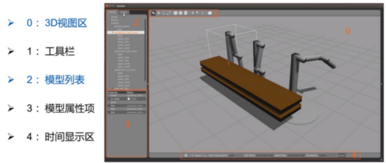
0: 3D view area
1: Toolbar
Buttons for selecting, moving, rotating and scaling objects; Create simple shapes (such as cubes, spheres, cylinders); And copy / paste
2: Model List
WORLD: displays the model currently in the scene, and allows you to view and modify the model parameters [anti theft mark – hzj]
INSERT: used to add new objects (models) to the simulation. To view a list of models, you may need to click the arrow to expand the folder. Click (and release) on the model you want to INSERT, and then click again in the scene to add the model
LAYERS: organize and display the different visualization groups (if any) available in the simulation
3: Model attribute item
4: Time display area
.
.
6, Interface function package of gazebo and ros
The elements of gazebo simulation are built with corresponding msgs and corresponding api functions. You can build them yourself by learning these
(1)gazebo_ros
 Mainly used for gazebo Interface encapsulation gazebo Startup of server and client URDF Model generation [anti theft mark]–Box Zijun hzj]

(2)gazebo_msgs
 Mainly gazebo Topic msg And services srv Data structure of

(3)gazebo_plugins
 Mainly used for gazebo Universal sensor plug-in

(4)gazebo_ros_api_plugins\gazebo_ros_path_plugins
 these two items. gazebo The plug-in implements the encapsulation of the interface
Official course
http://gazebosim.org/tutorials?tut=custom_messages&cat=transport
.
.
7, Steps to build simulation environment [key points!!!]
1. Server and client of gazebo
(the underlying engine of gazebo)
Server gzserver: a server used to simulate physics, rendering, and sensors
Client gzclient: a client that provides a graphical interface to visualize the simulation and interact with the simulation [anti theft mark – hzj]
The client and server communicate using the gazebo communication library
.
.
2. [environmental model file] build an environmental geometric model [. world/.sdf]
(all about environment configuration are here, including static objects, lights, etc.)
[this is usually built by yourself – in the form of. world model file]
(1) Environment geometry model catalog
(1)World object
 Such as buildings and lights

(2)static object
 Entities marked as static (in SDF Have<Static>true</Static>The entity of the element) is an object that has only collision geometry. All objects that do not intend to move should be marked as static

(3)Dynamic object
 Entity marked as dynamic (missing)<static>Element or in SDF Set as in false)Is an object with both inertia and collision geometry.
.
.
(2) Static simple scene construction
1. Method 1: directly use the model included in gazebo's GUI / download gazebo's model database, and then save it as a. world file
You can also modify parameters later
(1)[[quick build] Gazebo Interface GUI Provides a simple set of shapes: box, sphere, and cylinder
(2)[Very useful] Gazebo Model database model database It is a repository for all types of models, including robots, tables, and buildings
(3)After setting up the environment, select save from the file menu in the format.world File, to reopen, enter.world In the file directory, enter the command $gazebo XXX.world
Official course
[create environment] http://gazebosim.org/tutorials?tut=build_world&cat=build_world
[modify environment] http://gazebosim.org/tutorials?tut=modifying_world&cat=build_world
.
.
2. Method 2: use Building Editor to draw models (mainly walls and houses), and then save them as. world files
Select Edit –; Building Editor in the gazebo menu bar to open the Building Editor interface. Select the drawing option on the left, and then use the mouse to draw in the upper window. The drawn simulation environment can be displayed in real time in the lower window. [anti theft mark – hzj]
Refer to the official tutorial
http://gazebosim.org/tutorials?cat=build_world&tut=building_editor
.
.
3. Method 3: search the open source environment model on github and use it directly [it's better to build it yourself]
github~~
.
.
(3) Dynamic complex scene construction
Check the tutorials provided on the official website of gazebo, and generally use the world plug-in method to import
.
.
(4) How to modify the built. world file
Go to the purpose of placing the. World file, run the command $gazebo XXX.world, overwrite and save it after modification [anti theft mark - box type hzj]
.
.
be careful
(1) The simulation environment should be kept as simple as possible, otherwise it is difficult to solve problems
.
.
3. [robot model file] build robot geometric model [. urdf/.xacro]
(the structure and configuration of the robot body are all here, including the mechanical structure and geometric link relationship of the robot)
[if you can use other people's models, use other people's models - in the form of describe function package model file]
(0) principle of geometric model directory structure of robot / obstacle
(1) Connotation of model
	Can be programmed or through GUI Dynamically load the model into the simulation
	The model defines physical entities with dynamic, kinematic and visual characteristics
	A model may have one or more plug-ins that affect the behavior of the model–Box Zijun hzj]
(2) Directory structure of model database
(1)[[plug in] Plugins Directory
(2)[Geometry] Meshes Directory
(3)[[material] Material Directory
(4)Database Config
(5)Model Config
(6)Model SDF
(7)Model SDF.ERB
Gazebo relies on the model database to store and maintain the models available in the simulation. The model database is a resource supported by the community
git clone https://github.com/osrf/gazebo_models
.
.
(1) Simple robot / obstacle model construction [implemented by Model Editor of interface GUI of gazebo]
Note that this method is only suitable for using the Model Editor
(1) Mechanical shapes [simple shapes/custom shapes]
Method 1: use GUI Simple geometry to build a simple robot [anti-theft mark]–Box Zijun hzj]
Method 2: use SVG files Draw some small mechanical parts
Official course
http://gazebosim.org/tutorials?cat=model_editor_top&tut=extrude_svg
(2) Insert sensor [Model Database]
from gazebo Insert an existing sensor model into the model database

The first list contains the models available on the local machine

The second list contains gazebo Official models, more information will be displayed when they are downloaded from the online model database
(3) Add plug-ins [Model Plugins]
Simple plug-ins can be used gazebo Existing plug-ins and complex plug-ins can create their own plug-ins through programming–Box Zijun hzj]
(4) Finally, save the model through the GUI
Refer to the official tutorial
http://gazebosim.org/tutorials?cat=guided_b&tut=guided_b3
.
.
(2) Complex robot model construction [implemented with tools or programming]
1) Method 1: it is realized by simple URDF/xacro file programming
1. Name
Unified Robot Description Format Unified Robot Description Format
2. Advantages
1,Can parse URDF Used in files XML Robot model with format description [anti theft mark]–Box Zijun hzj]
2,ROS Also available URDF Document C++Parser
3. Robot structure decomposition
Connecting rod link
format:
<link name="<link name">
    <inertial>......</inertial>
    <visual>......</visual>
    <colliion>......</colliion>
<link>

Parameters:
  <inertial>:describe link Inertia parameter of: inertia matrix
  <visual>: describe link Appearance parameters of part: appearance, size and color
 <colliion>: describe link Collision attributes for: collision parameters
Joint
Format:
<joint name="joint name"type="joint type">
    <parent link="parent link"/>
    <child link="child link"/>
    <calibration......./>
    <dynamics....../>
    <limit....../>
    <....../>
</joint>

parameter
<parent link>:Connect the front link of the joint,Necessary
<child link>:Connect the rear link of the joint,Necessary
<calibration>:The reference position of the joint, which is used to calibrate the absolute joint position
<dynamics>:Describing the physical properties of joints, such as damping value and static friction, are often used in dynamic simulation–Box Zijun hzj]
<limit>:Describe the limit value of joint motion, including upper and lower limit position, speed limit, torque limit, etc
<mimic>:Describe the relationship between the joint and the existing joint
<safety _controller>:Describe safety controller parameters

Joint type
1,((important) continuous:Rotate the joint so that you can rotate infinitely around a single axis
2,((important) revolute:By rotating the joint, it can rotate at a limited angle around a single axis
3,prismastic:Smooth joints that can move along an axis with position constraints
 wait
4. Establishment of simulation model urdf practice (visualization of rviz model) [involving launch file]
2) Method 2: the proprietary scene parts are programmed by using SDF files
(1) Create environment shape model meshes
Method 1: search in Google's 3D Warehouse
The link is: https://3dwarehouse.sketchup.com/
Method 2: use three-dimensional modeling software to build the environment and import gazebo [anti theft mark – box hzj]
Blender,Sketchup,soildworks
(2) Writing. sdf environment files
Official course
http://gazebosim.org/tutorials?tut=build_model&cat=build_robot
.
.
3) Method 3: import through soilworks tool
Convert the design file into urdf file and then import it into the robot model [anti theft mark - box hzj]
.
.
4) Method 4: download open source from github and use it instead [I often use this method - stealing chicken]
be careful
(1) Create a robot and put it in the gazebo environment (URDF\Xacro, you can create it yourself or GitHub) [it's troublesome to build a model, because it's not accurate, just find it online]
.
.
(3) Two xacro models are connected to the same general xacro model
[used to connect the parent model (trunk) and child model (ARM) of the same robot]
[used to connect robot model and sensor model]
be careful
(1) Create a robot and put it in the gazebo environment (URDF\Xacro, you can create it yourself or GitHub) [it's troublesome to build a model, because it's not accurate, just find it online]
.
.
.
4. [build / use environment plug-in] [. Plug in]
(realize complex functions such as sensor data processing and control, including six types of plug-ins)
[embedded in the system and cannot be used alone] [anti theft mark - box hzj]
[if you can use other people's plug-ins, you can use other people's plug-ins - in the form of plug-ins]
(1) How to build your own plug-ins
1) Build a plug-in's generic method from scratch
Official tutorial 1
http://gazebosim.org/tutorials?tut=plugins_hello_world&cat=write_plugin
Official tutorial 2
http://gazebosim.org/tutorials?tut=ros_plugins&cat=connect_ros
.
.
.
2) Type, build + compile + use method of gazebo plug-in
At present, there are six types of plug-ins, and each plug-in type is managed by different components of Gazebo
(1) [environment scenario plug-in] World
World Plug in connected to World,control World Properties, such as physical engine, ambient lighting, and so on
 Official tutorial on building http://gazebosim.org/tutorials?tut=plugins_world&cat=write_plugin
(2) [robot Model plug-in – control]
Model Plug in connected to Gazebo And control the model, control the joints and the state of the model
 Official tutorial on building http://gazebosim.org/tutorials?tut=plugins_model&cat=write_plugin
(3) [Sensor plug-in] Sensor
Sensor Plug in to a specific sensor, obtain sensor information and control the sensor attribute [anti-theft mark]–Box Zijun hzj]
It will be explained in detail later
(4) [System plug-in] System
System The plug-in is specified on the command line and in the Gazebo Load first at startup. This plug-in allows users to control the startup process
 Official course http://gazebosim.org/tutorials?tut=system_plugin&cat=write_plugin
(5) [visualization plug-in] Visual
GUI The overlay is treated as transparent 2 at the top of the render window D Layer, visualization parameters
 Official course http://gazebosim.org/tutorials?tut=gui_overlay&cat=user_input
(6) [interface plug-in] GUI
.
.
.
3) Build a 32 wire lidar sensor plug-in from zero
[the plug-in can be used wherever it is built] [anti theft mark - box hzj]
Refer to the official tutorial
http://gazebosim.org/tutorials?cat=guided_i&tut=guided_i1
.
.
.
4) Basic method of testing plug-in (taking lidar as an example)
(1)Start roscore
source /opt/ros/<DISTRO>/setup.bash
roscore
(2)In a new terminal, start Gazebo
cd ~/velodyne_plugin/build
source /opt/ros/<DISTRO>/setup.bash
gazebo ../velodyne.world
(3)In a new terminal, use rostopic to send a velocity message.
source /opt/ros/<DISTRO>/setup.bash
rostopic pub /my_velodyne/vel_cmd std_msgs/Float32 1.0
.
.
.
(2) Methods of using plug-ins built by others [key points]
0) main principles and steps
(1) Step 1: in gazebo, you can insert some plug-ins to simulate the characteristics of the robot's sensors and actuators. These plug-ins are described by the labels in the elements
(2) Step 2: in the urdf/xacro.sdf file of the sensor, first include the sensor model (with plug-in) into the robot sub model by using the label, and then connect different models through the label
(3) Step 3: (only large models can do this, optional) first create a sensor model and configuration for the sensor with xacro file, and then embed the xacro model and configuration of the sensor into the robot's xacro file through secondary tags [anti theft tag - box type hzj]
Official course
http://gazebosim.org/tutorials?tut=add_laser&cat=build_robot
.
.
.
1) Using robot body plug-in
(1) [Model plug-in] trolley motion control plug-in
(1) Differential chassis drive insert
Many robot bodies adopt differential drive. Gazebo provides simulation plug-ins for differential robots. You can directly put the following codes into URDF files, modify corresponding parameters, and specify topics to be subscribed for motion control to make the robot move in gazebo
<gazebo>
  <plugin name="differential_drive_controller" filename="libgazebo_ros_diff_drive.so">
    <alwaysOn>true</alwaysOn>
    <updateRate>${update_rate}</updateRate>
    <leftJoint>base_link_right_wheel_joint</leftJoint>
    <rightJoint>base_link_left_wheel_joint</rightJoint>
    <wheelSeparation>0.5380</wheelSeparation>
    <wheelDiameter>0.2410</wheelDiameter>
    <torque>20</torque>
    <commandTopic>cmd_vel</commandTopic>
    <odometryTopic>odom</odometryTopic>
    <odometryFrame>odom</odometryFrame>
    <robotBaseFrame>base_footprint</robotBaseFrame>
  </plugin>
</gazebo>
(2) Set the speed (PID) plug-in in joint Jink and link link
In joint Jink And connecting rod link Set speed in [anti theft mark]–Box Zijun hzj]
Official course http://gazebosim.org/tutorials?tut=set_velocity&cat=
(3) Contact Sensor
The contact sensor detects a collision between two objects and reports the position of the force associated with the contact
 Official course http://gazebosim.org/tutorials?tut=contact_sensor&cat=sensors
(4) Joint force and torque sensor insert [Force/Torque Sensor]
Use force on joints/Torque sensor. This sensor publishes force and torque readings to the topic.
Official course http://gazebosim.org/tutorials?tut=force_torque_sensor&cat=sensors
(5) Universal control interface ros_control
Control general interface
 Official course http://gazebosim.org/tutorials?tut=ros_control&cat=connect_ros
(6) Gravity PID compensation plug-in
stay Gazebo Use the model plug-in for gravity compensation and how to supplement the built-in PID Joint controller
 Official course http://gazebosim.org/tutorials?tut=gravity_compensation&cat=plugins
(7) [model plug-in] JointEvent event trigger plug-in
When the position (or speed or applied force) of the joint enters or leaves the specified range, JointEvent Will be in sim_Send a message [anti theft tag] on the event subject–Box Zijun hzj]
Official course http://gazebosim.org/tutorials?tut=joint_events&cat=
.
.
.
(2) [Sensor plug-in] trolley Sensor
[xacro files can be nested]
Official course http://gazebosim.org/tutorials?tut=ros_gzplugins&cat=connect_ros
1. Simulated 2D Radar Data
Because the sample is in my knowledge base, it will be transferred later~
.
2. Simulation camera data
Because the sample is in my knowledge base, it will be transferred later ~ [anti theft mark – box hzj]
.
3. Simulated 3D lidar data
Because the sample is in my knowledge base, it will be transferred later~
.
4. Simulated RealSense binocular camera data
Because the sample is in my knowledge base, it will be transferred later~
.
5. Depth camera integration plug-in
Because the sample is in my knowledge base, it will be transferred later~
.
.
.
2) Using the world environment plug-in
(1) [world plug-in] dynamic human walking scene (actor)
[as a dynamic obstacle]
Blog tutorial http://gazebosim.org/tutorials?tut=actor#Scriptedtrajectories
Official course http://gazebosim.org/tutorials?tut=actor&cat=build_robot
.
(2) Specifies a random motion speed for any link in the world coordinate system
[Random Velocity Plugin] [as a dynamic obstacle] [anti theft mark – box hzj]
Specify a random speed for link s in the world. You can set the maximum and minimum allowable values of x, y and z speed components and speed amplitude. In addition, you can set a time period after which the speed can change itself. After setting speed amplitude, you will set the direction yourself
Official course http://gazebosim.org/tutorials?tut=plugins_random_velocity&cat=
.
(3) Obtain the positioning information of the robot in gazebo
Obtained in the form of plug-ins: plug-ins can be added to the urdf model of the robot
    <!-- Fake localization plugin -->
    <plugin name="ground_truth_odometry" filename="libgazebo_ros_p3d.so">
      <alwaysOn>true</alwaysOn>
      <updateRate>100.0</updateRate>
      <bodyName>base_link</bodyName>
      <topicName>base_pose_ground_truth</topicName>
      <gaussianNoise>0.01</gaussianNoise>
      <frameName>map</frameName>-->
        <!-- initialize odometry for fake localization-->
      <xyzOffsets>0 0 0</xyzOffsets>
      <rpyOffsets>0 0 0</rpyOffsets>
    </plugin>
Get as subscriber
Subscribe to the topic / gazebo/model_states and find the name of the corresponding model
[anti theft mark – box hzj]
void _modelStatesCallback(const gazebo_msgs::ModelStatesConstPtr &msg)
{
  int modelCount = msg->name.size();

  for(int modelInd = 0; modelInd < modelCount; ++modelInd)
  {
      if(msg->name[modelInd] == "turtlebot3")
      {
          _current_pose.pose = msg->pose[modelInd];
          _current_velocity.twist = msg->twist[modelInd];
          break;
      }
  }
}
.
(4) Event based triggering
(1) [world plug-in] Occupied Event
Whenever the model occupies the specified three-dimensional area, OccuppiedEvent will send a message about the subject [anti theft mark – box hzj]
Official course
.http://gazebosim.org/tutorials?tut=occupiedevent&cat=plugins
(2) [world plug-in] Trigger an Action in the environment
Official course
http://gazebosim.org/tutorials?tut=contain_plugin&cat=plugins
.
.
3) [visualization plug-in] Visual
effect
The GUI overlay is treated as a transparent 2D layer at the top of the rendering window, visualizing the parameters
Official course
http://gazebosim.org/tutorials?tut=gui_overlay&cat=user_input
be careful
What functions do the simulation plug-ins of gazebo of ROS need? You can find the plug-ins on the official website or wiki [anti theft mark - box king hzj]
.
.
.
5. Import the required items of relevant gazebo through the launch file [gazebo.launch]
(all about starting the gazebo component are here)
[this is usually implemented by yourself – gazabo's launch]
First level demo_run.launch
[this launch is to start the whole project]
Startup of other modules
<!---Gazebo---->
<include file="$(gazebo Function package)/.../launch/gazebo.launch">
.
.
Secondary gazebo.launch
[this launch is dedicated to gazebo]
(1) Open the World Models simulation environment using the roslaunch command
1)Command (without parameters): roslaunch gazebo.launch
2)Command (with parameters): roslaunch gazebo_ros empty_world.launch paused:=true use_sim_time:=false gui:=true throttled:=false recording:=false debug:=true verbose:=true gui_required:=true
(2) The principle of writing gazebo.launch
(1)[[geometric environment loading] world Principle of file loading
 First create an empty empty gazebo Environment, and then through world_name load.world The path of the file is marked–Box Zijun hzj]

(2)[Robot model file loading] xacro File loading principle
 The robot model is usually downloaded from the Internet. It is already a function package with sensors and control plug-ins, such as re launch Start a feature pack on the, so you can start it

(3)[[loading of plug-in file]
Plug in files are usually embedded in world Geometric environment and model In the robot model, the specific operation depends on the chapter on the use of the plug-in,
The plug-ins with models will not be used independently. Some visual plug-ins of independent systems can,
as rqt_steering Plug in( rqt The toolkit has many independent plug-ins) robot_state_publisher(For publishing TF)

(4)......
.
.
(3) gazebo.launch usually starts steps of type
Starting the gazebo environment is also to start a general launch, and then start a pile of simulation related mechanical shape, control, sensor data, environment data, plug-in data and coordinate conversion!
(1) [Environmental geometric model] set the parameters of gazebo (the most commonly used one)
If not set, use the default parameters
paused  Start in suspended state Gazebo(Default to false)
use_sim_time  inform ROS Node requests time to get pass ROS theme/Clock released Gazebo Simulation time for publishing (default is true)
gui  start-up Gazebo User interface window (default is true)
gui_required  When gzclient(Terminate the startup script when the user interface window exits (the default is false)
headless  Enable gazebo Status logging
debug  Start gzserver (Gazebo Server) in debug mode using gdb (default false)
verbose use--verbose function gzserver and gzclient,Print errors and warnings to the terminal (default is false)
server_required  When gzserver(Gazebo The server) terminates the startup script on exit (default = 0) false)
world_name  This is what we built.world Directory of files
(2) [robot model] load the robot model xacro (robot_description) in gazebo
(3) [plug in] run the robot_state_publisher node to publish TF
(4) [insert] loading trolley controller rqt#u steering
(5) [plug in] start rqt steering GUI [plug in]
...
Official course
http://gazebosim.org/tutorials?tut=ros_roslaunch&cat=connect_ros
6. Build the ROS project and write the source code with the ROS project
[system development foundation reserve] ROS development steps (Part II)
It's the same as the steps in the blog above. Let's move on~
.
.
7. Obtain the simulation data from gazebo
[in the form of. rviz, plug-ins and subscribers]
(implement your own source code before obtaining data)
(1) Build rviz visualization configuration file [. Rviz]
(for data visualization, please refer to rviz, and for simulation environment, please refer to gazebo) [anti theft mark – hzj]
If you configure it in rviz, you can export the file directly. The simulation data is obtained in the form of plug-ins, including control plug-ins, sensor plug-ins and environment plug-ins
be careful
Generally, you can't see the specific effect in gazebbo. You can turn off the interface of gazebo, which consumes too much computational effort
The data of the model and scene visualized by rviz and gazebo are obtained through the parameter server, not by receiving topics
(2) Through the GUI of gazebo, the published topics are displayed
(3) Screenshot of gazebo
.
.
.
8, Attention
gazebo's coordinate system uses a right-hand coordinate system
Common problems in gazebo
Frequently turning on and off the gazrbo simulation environment will report an error, because gazebo is turned on again when it does not completely exit (especially for junk computers) [anti theft mark - box king hzj]
terms of settlement
$killall gzserver
$killall gzclient
reference material
(1) gazebo tutorial: http://www.gazebosim.org/tutorials
(2) What functions you need can be searched on the official website of gazebo and deployed according to the Tutorials of wiki and Tutorials
(3) For specific reference projects, or to steal the source code, you can directly run the official tutorial, deploy it, and analyze how it is implemented