Experimental task 1
Task 1-1
- task1_1.asm source code
 1 assume ds:data, cs:code, ss:stack
 2
 3 data segment
 4     db 16 dup(0)
 5 data ends
 6
 7 stack segment
 8     db 16 dup(0)
 9 stack ends
10 code segment
11 start:
12     mov ax, data
13     mov ds, ax
14
15     mov ax, stack
16     mov ss, ax
17     mov sp, 16
18
19     mov ah, 4ch
20     int 21h
21 code ends
22 end start
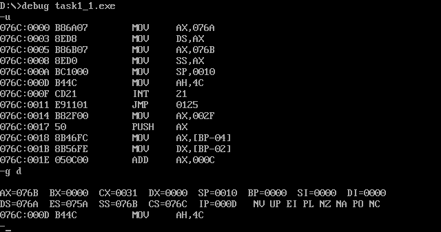
- task1_1 screenshot before the end of line17 and line19
- question answering
1. In debug, execute until the end of line17 and before line19. Record this time: register (DS) = 076A, register (SS) = 076B, register (CS) = 076C
2. Assuming that the segment address of the code segment is X after the program is loaded, the segment address of the data segment is X-2 and the segment address of the stack is X-1.
Task 1-2
- Task task1_2.asm source code
 1 assume ds:data, cs:code, ss:stack
 2
 3 data segment
 4     db 4 dup(0)
 5 data ends
 6
 7 stack segment
 8     db 8 dup(0)
 9 stack ends
10 code segment
11 start:
12     mov ax, data
13     mov ds, ax
14
15     mov ax, stack
16     mov ss, ax
17     mov sp, 8
18
19     mov ah, 4ch
20     int 21h
21 code ends
22 end start
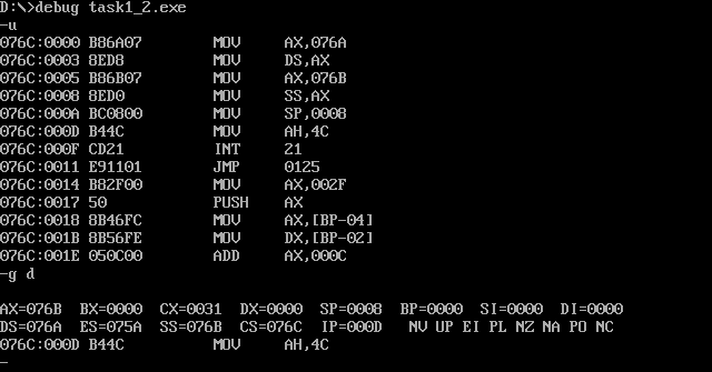
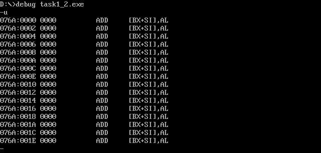
- task1_2. After debugging to the end of line17 and before line19, observe the screenshot of register DS, CS and SS values
- question answering
1. In debug, execute until the end of line17 and before line19. Record this time: register (DS)= 076A, register (SS)= 076B, register (CS)= 076C
2. Assuming that the segment address of the code segment is X after the program is loaded, the segment address of the data segment is X-2 and the segment address of the stack is X-1.
Task 1-3
- Task task1_3.asm source code
 1 assume ds:data, cs:code, ss:stack
 2
 3 data segment
 4     db 20 dup(0)
 5 data ends
 6
 7 stack segment
 8     db 20 dup(0)
 9 stack ends
10 code segment
11 start:
12     mov ax, data
13     mov ds, ax
14
15     mov ax, stack
16     mov ss, ax
17     mov sp, 20
18
19     mov ah, 4ch
20     int 21h
21 code ends
22 end start
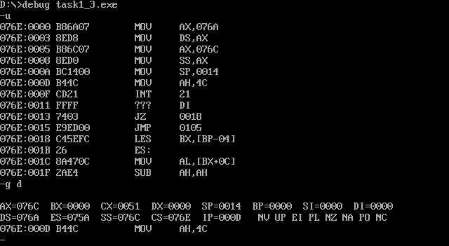
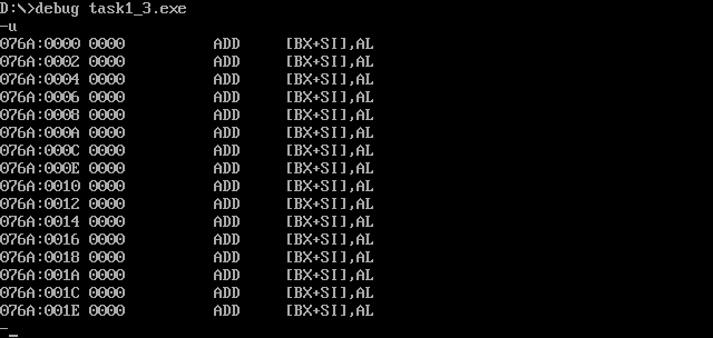
- task1_3. Screenshot of the values of registers DS, CS and SS before the end of debugging to line17 and line19
- question answering
1. In debug, execute until the end of line17 and before line19. Record this time: register (DS)= 076A, register (SS)= 076C, register (CS)= 076E
2. Assuming that the segment address of the code segment is X after the program is loaded, the segment address of the data segment is X-4 and the segment address of the stack is X-2.
Tasks 1-4
- Task task1_4.asm source code
 1 assume ds:data, cs:code, ss:stack
 2 code segment
 3 start:
 4     mov ax, data
 5     mov ds, ax
 6
 7     mov ax, stack
 8     mov ss, ax
 9     mov sp, 20
10
11     mov ah, 4ch
12     int 21h
13 code ends
14
15 data segment
16     db 20 dup(0)
17 data ends
18
19 stack segment
20     db 20 dup(0)
21 stack ends
22 end start
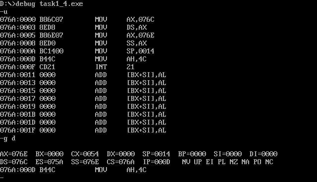
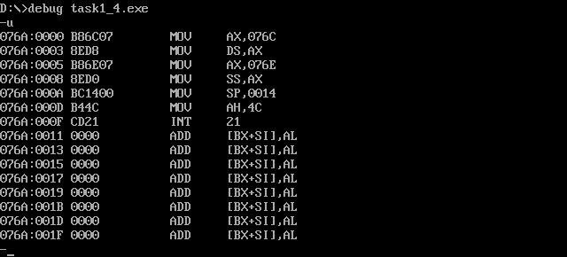
- task1_4. After debugging to the end of line17 and before line19, observe the screenshot of register DS, CS and SS values
- question answering
1. In debug, execute until the end of line17 and before line19. Record this time: register (DS)= 076C, register (SS)= 076E, register (CS)= 076A
2. Assuming that the segment address of the code segment is X after the program is loaded, the segment address of the data segment is X+2 and the segment address of the stack is X+4.
Tasks 1-5
Based on the practice and observation of the above four experimental tasks, summarize and answer:
1. For the segment defined below, after the program is loaded, the actual memory space allocated to the segment is INT((N+15)/16)*16.
1 xxx segment
2     db N dup(0)
3 xxx ends
2. If the program Task1_ 1.asm, task1_ 2.asm, task1_ 3.asm, task1_ 4. In ASM, if the pseudo instruction end start is changed to end, which program can still be executed correctly. The reasons are analyzed and explained in combination with the conclusions obtained from practical observation.
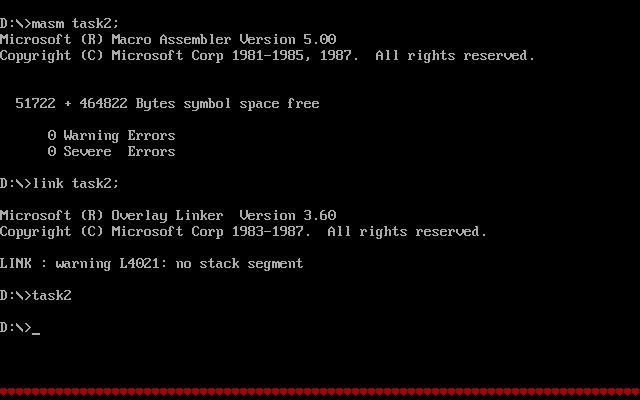
Answer: as shown in the figure:

Only program 4 can execute correctly. The reason is that end followed by start indicates that the entry of the program is at start (in other words, it is OK to replace start with other labels). If start is omitted, the first address of the code segment will default to 076A:0. Programs 1, 2 and 3 declare the data segment first, that is, starting from 076A:0, the memory space is allocated to the data segment and stack segment first, and then to the code segment. The first address of the code segment is not at 076A:0, Therefore, it cannot be executed correctly; Program 4 declares the code segment first. The first address of the code segment just starts from 076A:0, so the start program can be executed correctly without starting.
Experimental task 2
- Assembly source code
 1 assume cs:code
 2 code segment
 3 start:
 4     mov ax, 0b800h
 5     mov ds, ax
 6     mov bx, 0f00h
 7     mov cx, 160
 8     mov ax, 0403h
 9 s:  mov [bx],ax
10     add bx, 2
11     loop s
12
13 mov ax,4c00h
14 int 21h
15 code ends
16 end start
- Screenshot of operation results
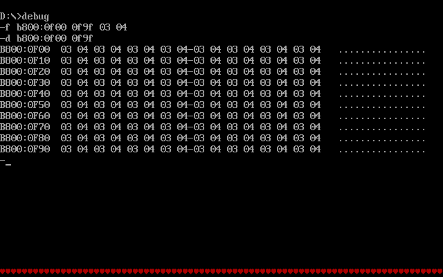
As shown in the figure, the final running result is consistent with experiment 1 and experiment task 3.
Experimental task 3
- Complete assembly source code
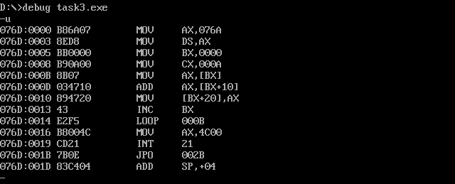
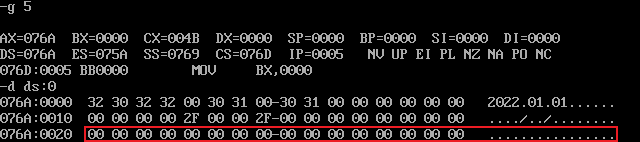
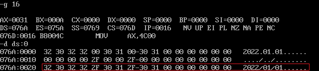
 1 assume cs:code
 2 data1 segment
 3     db 50, 48, 50, 50, 0, 48, 49, 0, 48, 49 ; ten numbers
 4 data1 ends
 5
 6 data2 segment
 7     db 0, 0, 0, 0, 47, 0, 0, 47, 0, 0       ; ten numbers
 8 data2 ends
 9
10 data3 segment
11     db 16 dup(0)
12 data3 ends
13
14 code segment
15 start:
16     mov ax, data1
17     mov ds, ax
18     mov bx, 0
19     mov cx, 10
20 s:  mov ax, [bx]
21     add ax, [bx+10h]
22     mov [bx+20h], ax
23     inc bx
24     loop s
25
26 mov ax, 4c00h
27 int 21h
28 code ends
29 end start
- Load, disassemble and debug screenshots in debug
Before adding data items in turn, check the debug command and screenshot of the original value of memory space data corresponding to logical segments data1, data2 and data3
After adding in sequence, view the debug command and screenshot of the memory space data values corresponding to logical segments data1, data2 and data3
Experimental task 4
- Complete assembly source code
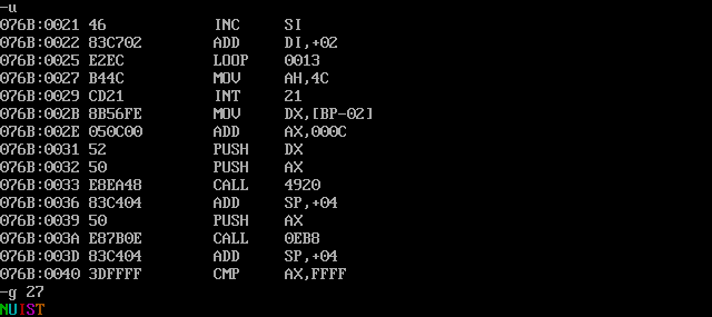
 1 assume cs:code
 2
 3 data1 segment
 4     dw 2, 0, 4, 9, 2, 0, 1, 9
 5 data1 ends
 6
 7 data2 segment
 8     dw 8 dup(0)
 9 data2 ends
10
11 code segment
12 start:
13     mov ax, data1
14     mov ds, ax
15     mov ax, data2
16     mov ss, ax  ;hold data2 Make stack segment
17     mov sp, 10h ;Set the stack top pointer. When pressing the stack, the word pressing the stack first is stored at the bottom of the stack, that is, after the data segment, sp=sp-2,So as to realize reverse order storage
18     mov bx, 0
19     mov cx, 8
20 s:  push [bx]
21     add bx, 2
22     loop s
23
24     mov ah, 4ch
25     int 21h
26 code ends
27 end start
- Load, disassemble and debug screenshots in debug
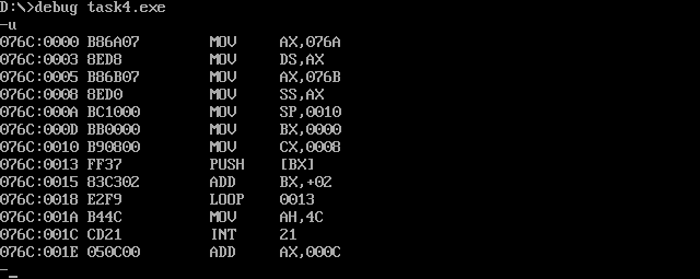
Before the program exits, use the d command to view a screenshot of the memory space corresponding to data segment data2.

Experimental task 5
- task5.asm source code
 1 assume cs:code, ds:data
 2 data segment
 3         db 'Nuist'
 4         db 2, 3, 4, 5, 6
 5 data ends
 6
 7 code segment
 8 start:
 9         mov ax, data
10         mov ds, ax
11
12         mov ax, 0b800H
13         mov es, ax
14
15         mov cx, 5
16         mov si, 0
17         mov di, 0f00h
18 s:      mov al, [si]
19         and al, 0dfh
20         mov es:[di], al
21         mov al, [5+si]
22         mov es:[di+1], al
23         inc si
24         add di, 2
25         loop s
26
27         mov ah, 4ch
28         int 21h
29 code ends
30 end start
- Screenshot of operation results

- Use the debug tool to debug the program, and use the g command to execute the screenshot before the program returns (i.e. after ine25 and before line27)
- The function of line19 in the source code is to change the 5th position of the ASCII code corresponding to the letter to 0 through the operation, that is, the uppercase letter to lowercase letter.
- What is the purpose of the byte data in the data segment line4 in the source code?
A: modify the value of 5 byte units in line4, and reassemble, link and run again.
1 db 2,3,4,5,6
2 --> Change to:
3 db 5 dup(2)
The results are shown in the figure:

It is not difficult to see that these byte data are used to adjust the character color.
Experimental task 6
- task6.asm source code
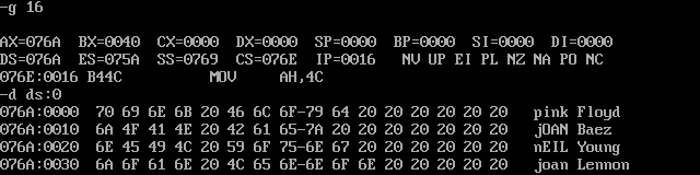
 1 assume cs:code, ds:data
 2
 3 data segment
 4     db 'Pink Floyd      '
 5     db 'JOAN Baez       '
 6     db 'NEIL Young      '
 7     db 'Joan Lennon     '
 8 data ends
 9
10 code segment
11 start:
12     mov ax, data
13     mov ds, ax
14     mov bx, 0
15     mov cx, 4
16 s:  mov al, ds:[bx]
17     or al, 20h
18     mov ds:[bx], al
19     add bx, 16
20     loop s
21
22     mov ah, 4ch
23     int 21h
24 code ends
25 end start
- Load, disassemble and debug screenshots in debug
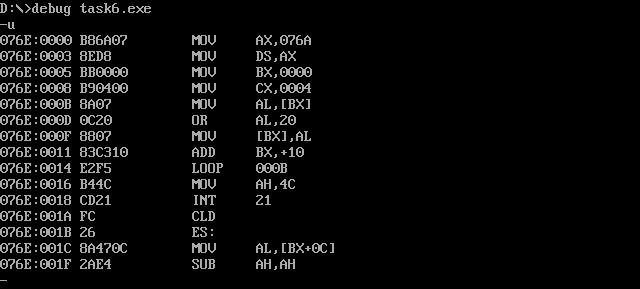
Before the program exits, use the d command to view a screenshot of the memory space corresponding to the data segment data.
Experimental task 7
- task7.asm source code
 1 assume cs:code, ds:data, es:table
 2
 3 data segment
 4     db '1975', '1976', '1977', '1978', '1979'
 5     dw  16, 22, 382, 1356, 2390
 6     dw  3, 7, 9, 13, 28
 7 data ends
 8
 9 table segment
10     db 5 dup( 16 dup(' ') )  ;
11 table ends
12
13 code segment
14 start:
15     mov ax, data
16     mov ds, ax
17     mov ax, table
18     mov es, ax
19     mov bx, 0
20     mov di, 0
21     mov cx, 5
22 s1: mov ax, ds:[bx]
23     mov es:[di], ax
24     mov ax, ds:[bx+2]
25     mov es:[di+2], ax
26     add bx, 4
27     add di, 10h
28     loop s1 ;Year copy
29
30     mov bx, 20
31     mov di, 5
32     mov cx, 5
33 s2: mov ax, ds:[bx]
34     mov es:[di], ax
35     mov word ptr es:[di+2], 0
36     add bx, 2
37     add di, 16
38     loop s2 ;Revenue copy
39
40     mov bx, 30
41     mov di, 10
42     mov cx, 5
43 s3: mov ax, ds:[bx]
44     mov es:[di], ax
45     add bx, 2
46     add di, 16
47     loop s3 ;Number of copies
48
49     mov di, 5
50     mov cx, 5
51 s4: mov ax, es:[di]
52     mov dx, 0
53     div word ptr es:[di+5]
54     mov es:[di+8], ax
55     add di, 16
56     loop s4 ;Per capita income
57
58     mov ah, 4ch
59     int 21h
60 code ends
61 end start
- Debug screenshot
- View screenshot of original data information of table segment
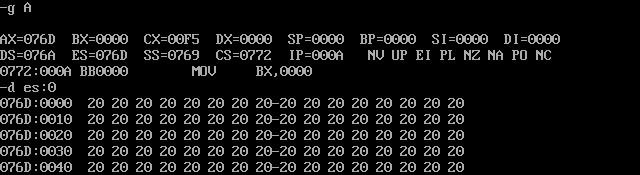
Run in debug until the program exits, and use the d command to view a screenshot of the memory space corresponding to the table segment.
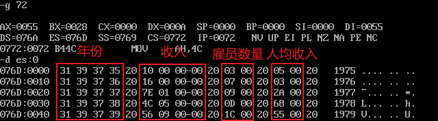
Inspection:
1. The data structure meets the requirements.
2. Per capita income: in decimal system, 16 / 3 = 5, 22 / 7 = 3382 / 9 = 421356 / 13 = 1042390 / 28 = 85, which are converted into hexadecimal: 05, 03, 2a, 68 and 55 respectively, so the data is correct.
Experimental summary
1. Through this experiment, we have a deeper understanding of the relevant knowledge of data segment memory space allocation. During memory allocation, the system does not allocate just the right memory space according to the needs of users, but allocates 16 bytes of memory as a unit.
2. In the process of coding, I am more familiar with some registers, especially the address registers bx,si,di, etc. and the register cx recording the number of cycles.
3. Master the declaration of some data types, such as byte data db, word data dw and double word data dd.