Article content:
One pin of the GPIOA end of the stm32F103 core board is connected to an LED, and one pin of the GPIOB port is connected to a switch (replaced by DuPont line simulation). Interrupt mode programming is adopted. When the switch is connected to high level, the LED lights up; When connected to low level, the LED is off. And use the middle section to complete a USART serial communication program of STM32
catalogue
2. Use interrupt mode to light LED
4.1 establishment of the project
1. Middle section
1.1 meaning
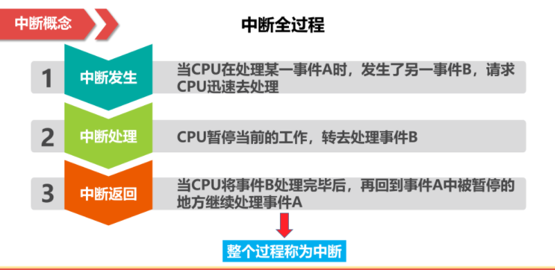
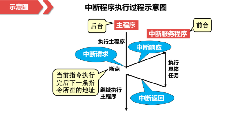
The CPU temporarily stops the execution of the current program, turns to handle the temporary events, and returns to execute the original program after processing. Interrupt is a process that calls the corresponding handler (or service program) when an external event occurs. The interrupt service program and the program that the CPU is running at the time of interrupt are independent of each other and do not transfer data to each other.
1.2 intermediate process
1.3 function
1. Preemptive priority
2. Responsive priority
The characteristic of preemptive priority is that interrupts with high preemptive priority can be responded in the process of interrupt processing with low preemptive priority, that is, interrupt nesting.
2. Use interrupt mode to light LED
2.1CubeMX generation project
Create a new project
Select STM32F103C8 chip and click Start Project to enter the project
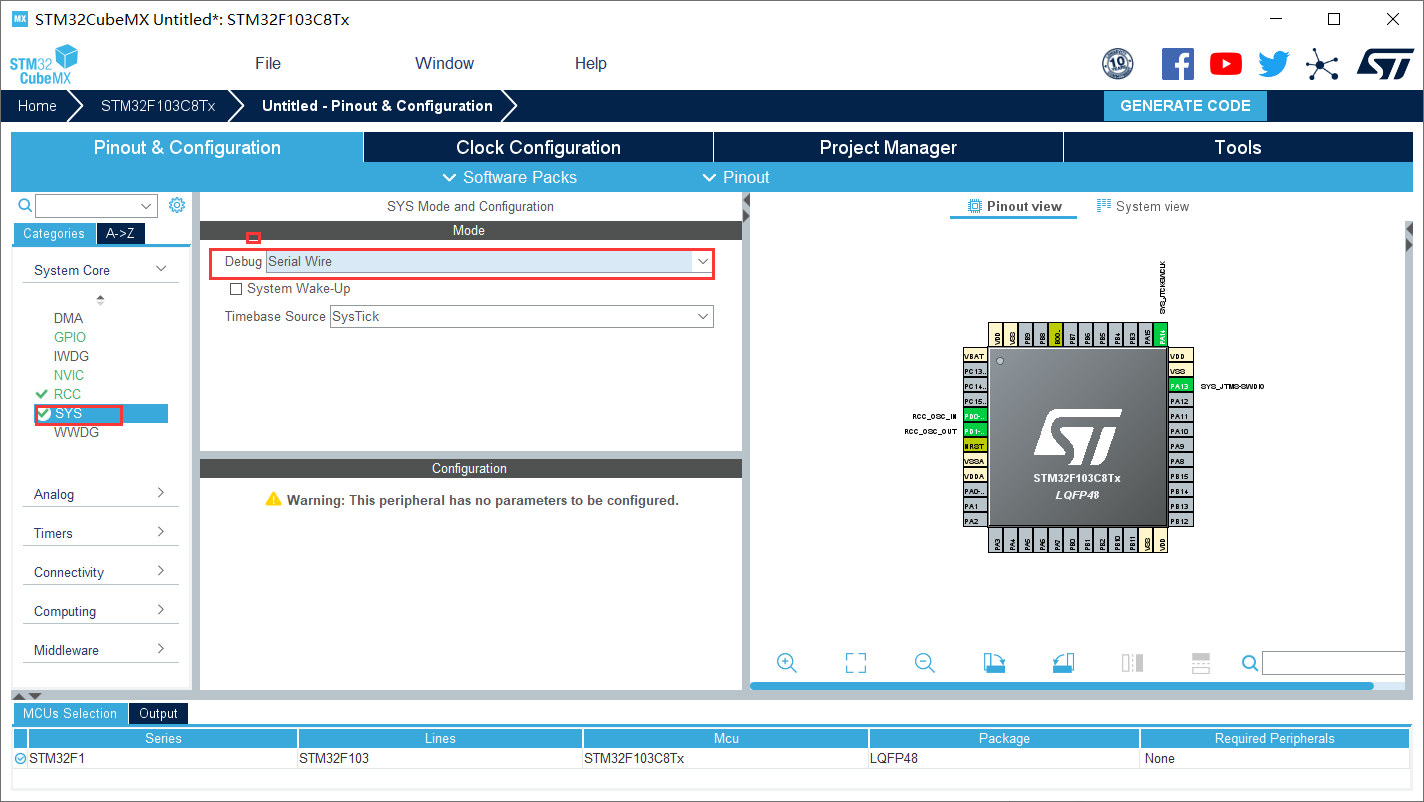
Configure the system debugging interface SYS and select Serial Wire
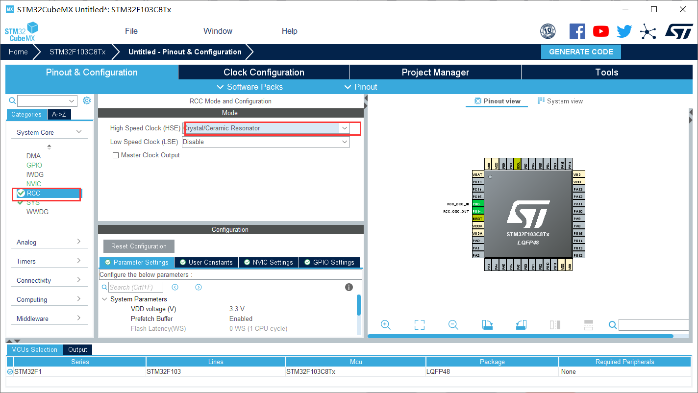
Configure the peripheral RCC and select HSE (external high-speed clock) as Crystal/Ceramic Resonator
2.2GPIO
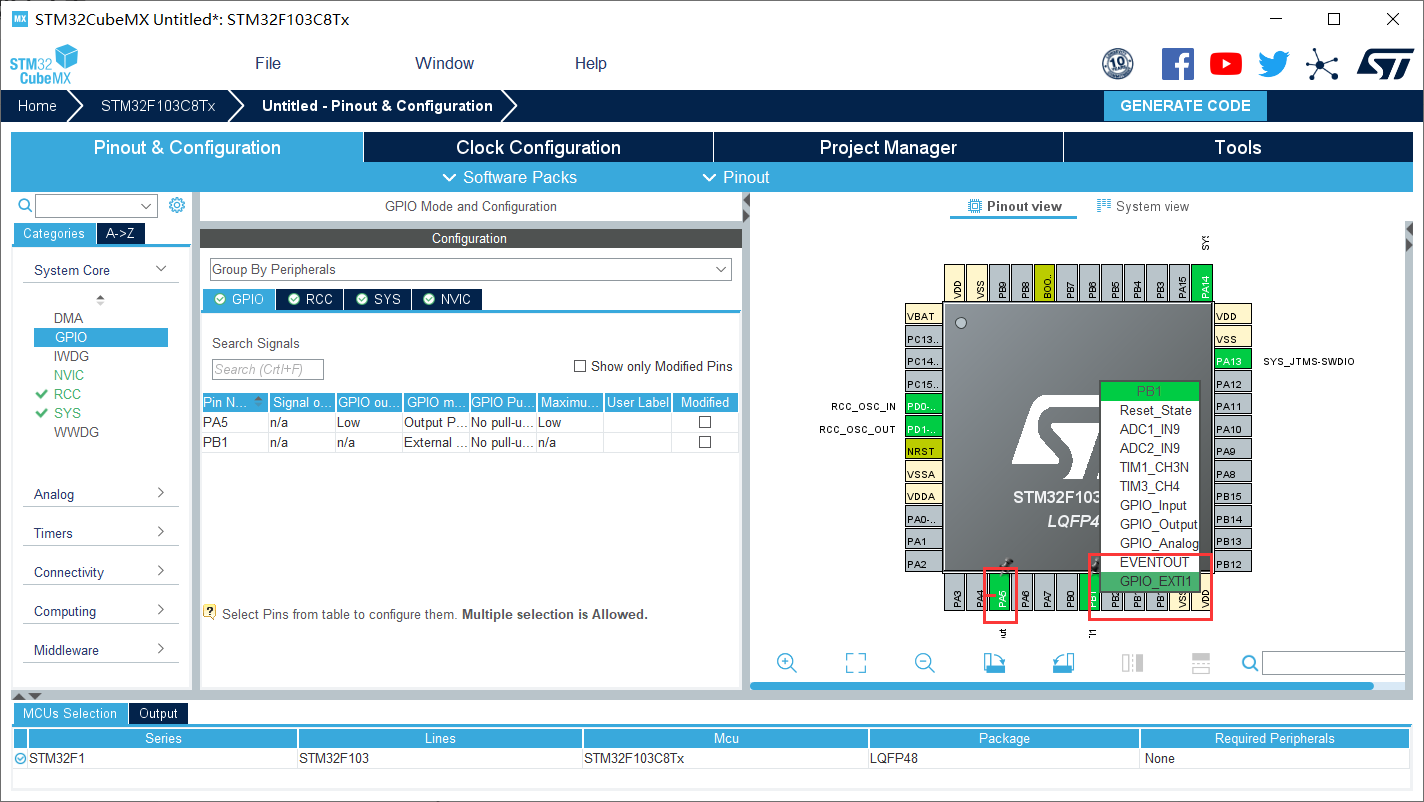
Select LED pin PA5 and set pin to output mode GPIO_Output
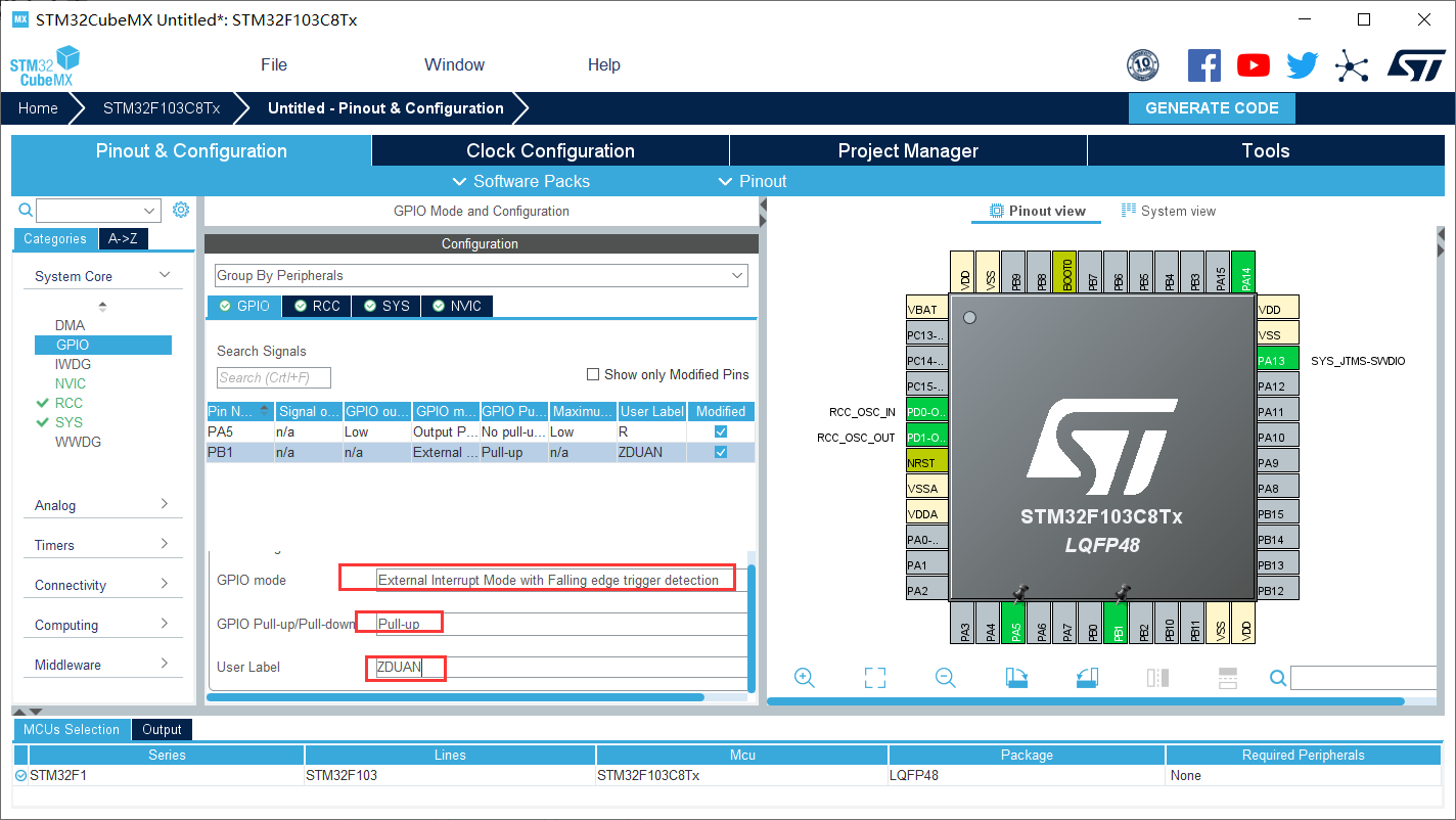
Select pin PB1 as an external interrupt and set it to GPIO with the interrupt line_ Exti15 connection
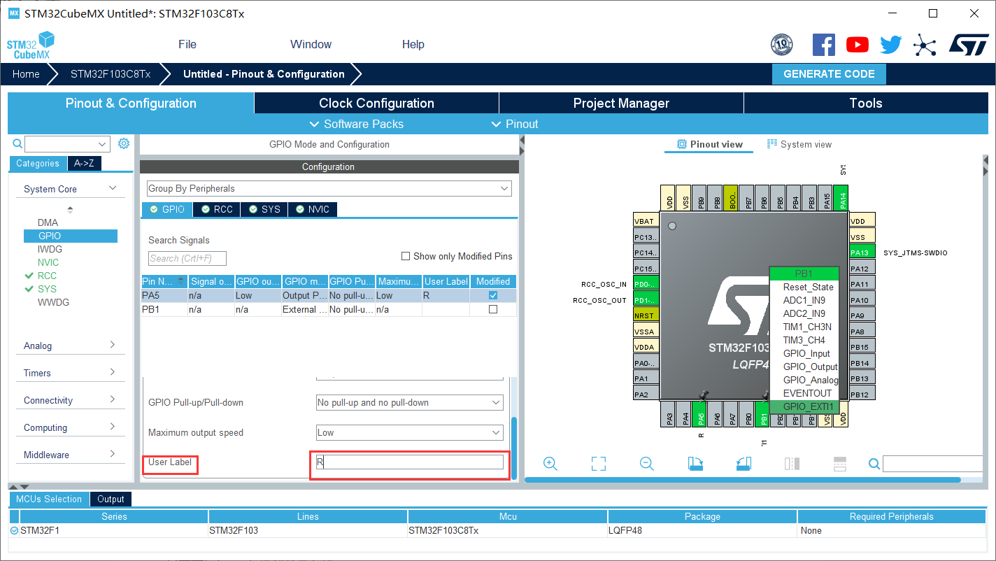
GPIO_PA5 is named R
GPIO_PB1 It is named ZDUAN, and the trigger mode is selected as falling edge trigger , Select pull-up resistance
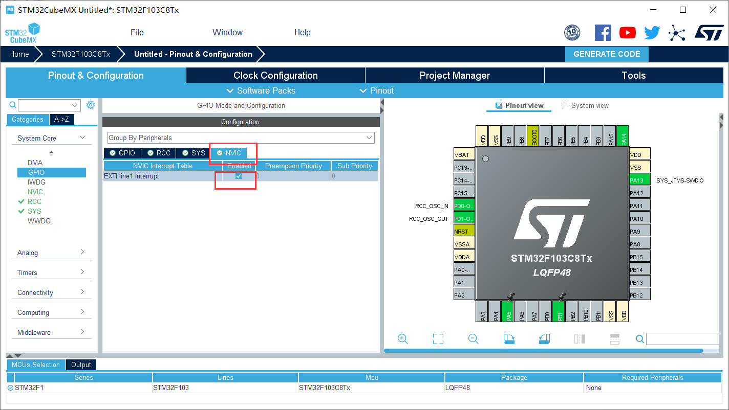
Select NVIC
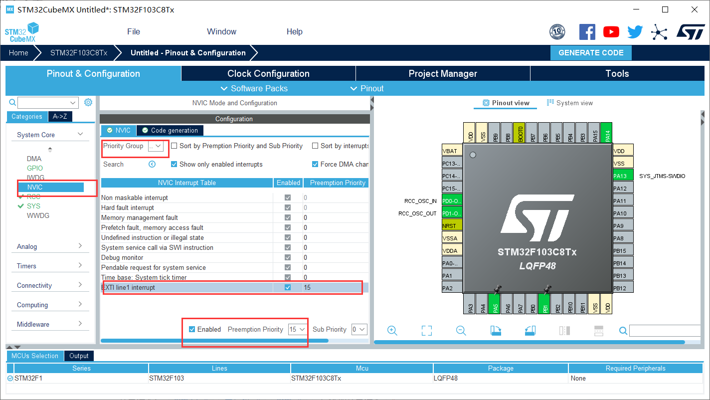
Set interrupt priority
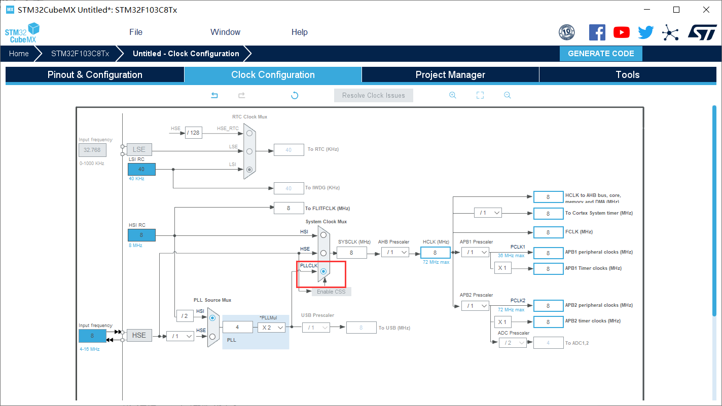
set clock
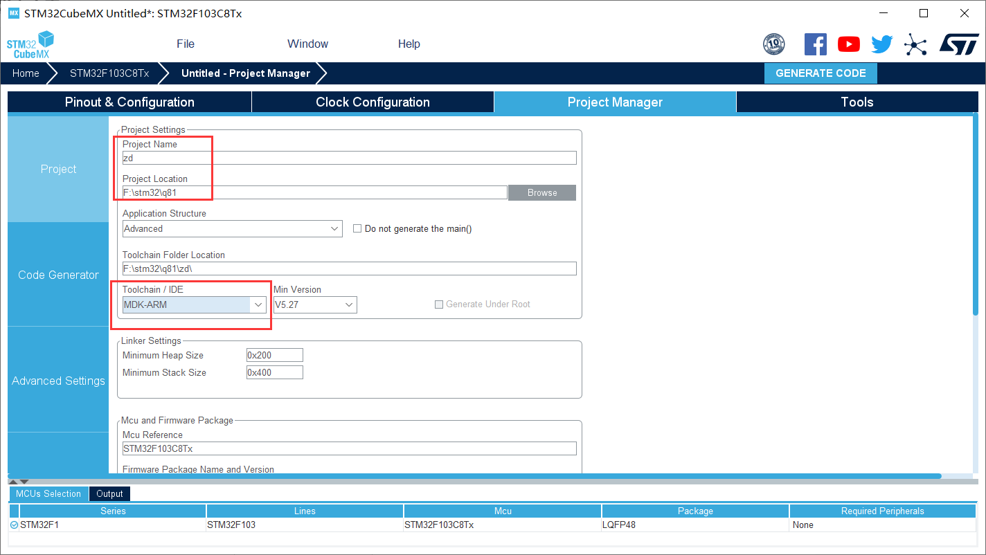
 Finally, the keil5 project is generated
3. Burning procedure
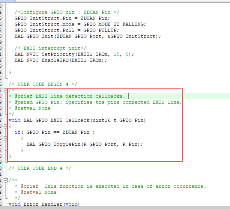
3.1 add code
The code is as follows
/*
* @brief EXTI line detection callbacks.
* @param GPIO_Pin: Specifies the pins connected EXTI line,
* @retval None
*/
void HAL_GPIO_EXTI_Callback(uint16_t GPIO_Pin)
{
	if( GPIO_Pin == ZDUAN_Pin )
		{
			HAL_GPIO_TogglePin(R_GPIO_Port, R_Pin);
		}
} 
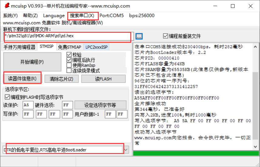
3.2 burning procedure
3.3 effect display
Note: since there is no switch, the middle section operation can only be carried out by wire grounding and non grounding instead of the switch
4. Serial communication
4.1 establishment of the project
Create a new project first, and the steps are the same as above
Setting RCC
Set SYS
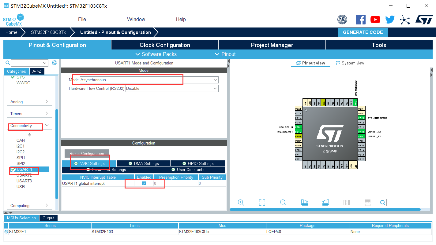
 Select UASRT1, change the mode to asynchronous communication, and select NVIC Setting below
Create project as above
4.2 code
First, define the length of an array to place the transmitted data
uint8_t OT_RxBuffer;
uint8_t Uart1_RxBuff[1000];
uint8_t Uart1_Rx_Cnt = 0;
Write acceptance function
HAL_UART_Receive_IT(&huart1, (uint8_t *)&OT_RxBuffer, 1);
Enable function and send function
void HAL_UART_RxCpltCallback(UART_HandleTypeDef *huart)
{
  /* Prevent unused argument(s) compilation warning */
  UNUSED(huart);
  /* NOTE: This function Should not be modified, when the callback is needed,
           the HAL_UART_TxCpltCallback could be implemented in the user file
   */
		Uart1_RxBuff[Uart1_Rx_Cnt++] = OT_RxBuffer;   //??????

		if((Uart1_RxBuff[Uart1_Rx_Cnt-1] == 0x0A)&&(Uart1_RxBuff[Uart1_Rx_Cnt-2] == 0x0D))
		{
			HAL_UART_Transmit(&huart1, (uint8_t *)&Uart1_RxBuff, Uart1_Rx_Cnt,0xFFFF);
			Uart1_Rx_Cnt = 0;
			//memset(Uart1_RxBuff,0x00,sizeof(Uart1_RxBuff));
		}

	HAL_UART_Receive_IT(&huart1, (uint8_t *)&OT_RxBuffer, 1);
}
Compiler
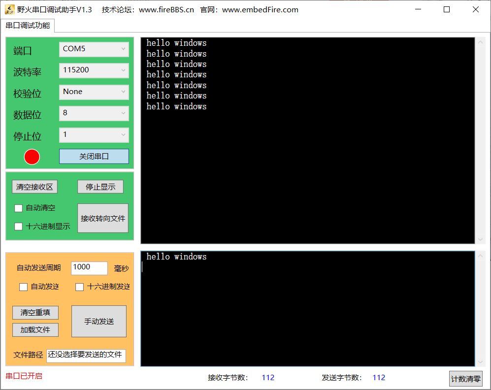
4.3 burning procedure
The final results are as follows
V. summary
Through this experiment, I realized the light on and off with CUbeMX and the serial communication with the middle section, and learned some relevant knowledge of the middle section
Vi. references
HAL library STM32CubeMX realizes LED on and off - interrupt mode_ Blog of L-GRAZY - CSDN blog