catalogue
1, Generate keil project using stm32subemx
1.3 initialization configuration
2, Improvement and Simulation in keil
3, stm32usart serial communication
1, Generate keil project using stm32subemx
1.1. Download stm32cupemx
You can register on the official website and download: https://www.java.com/en/download/manual.jsp
Detailed steps refer to: (53 messages) [STM32] STM32 CubeMx use tutorial I -- Installation Tutorial_ Z Xiaoxuan CSDN blog_ stm32cubemx installation
It's best to download the latest version, and then download the required chip. This time I downloaded stm32f1
1.2. Create a new project
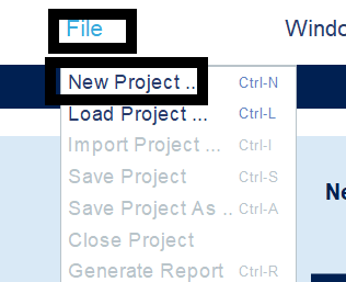
Open the installed stm32cubemx and create a new project
Select the chip you just downloaded, and then double-click Board at the bottom right to display the chip:
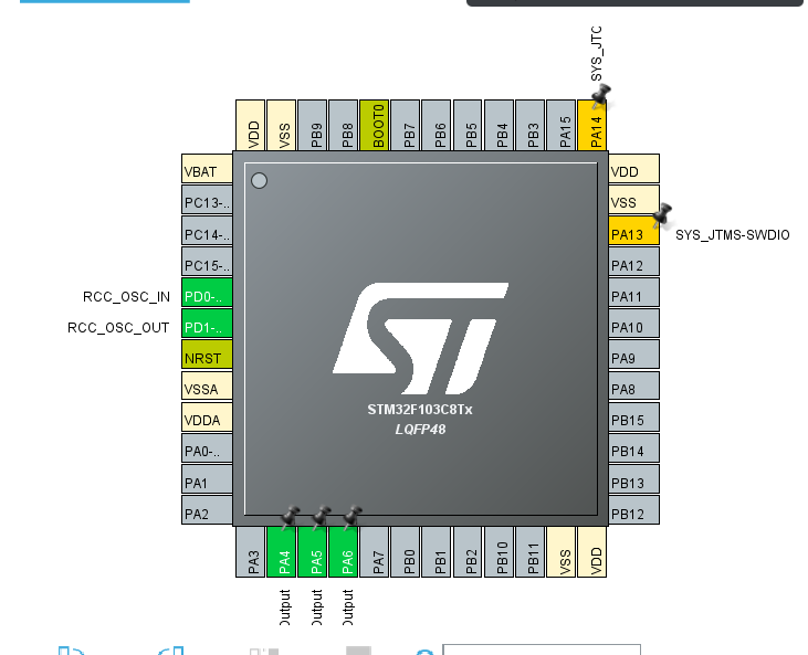
1.3 initialization configuration
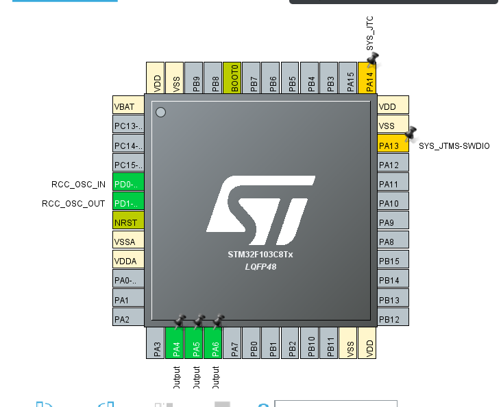
Start to initialize and configure the pins and clock of the chip. The pins can be selected according to their own needs. Select here
PA4\PA5\PA6: (as shown in the figure, PA5\PA6 operates the same as PA4)
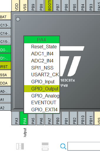
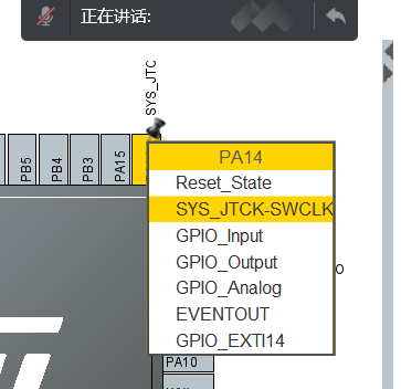
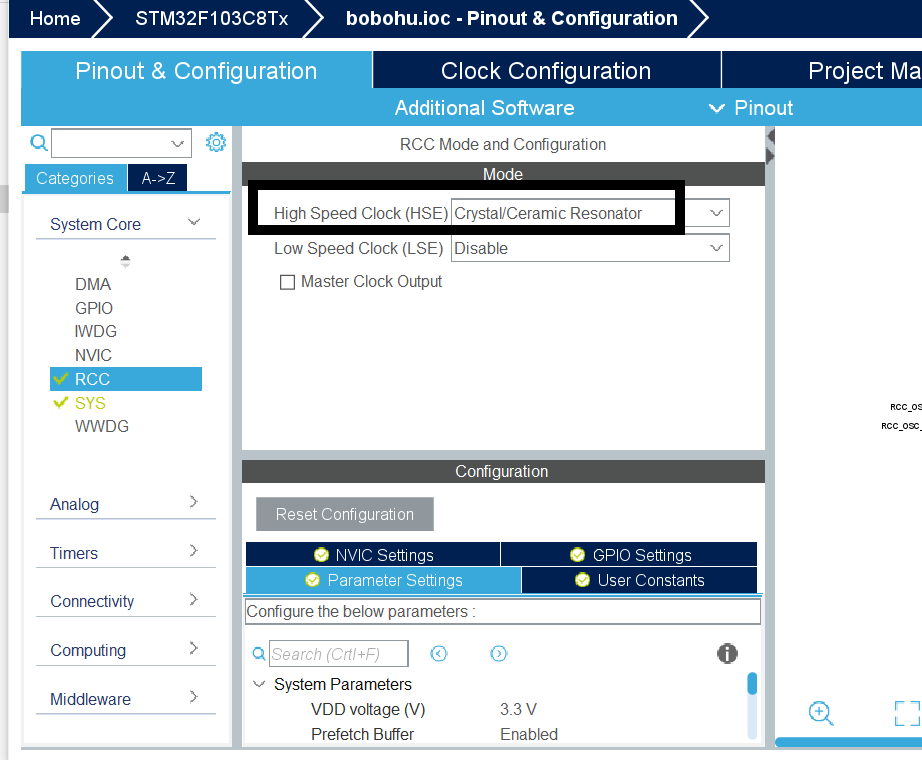
Then configure the clock and select the crystal oscillator:
Then change the 8mhz in the middle of the clock tree to 72mhz and enter: (select ok directly for the pop-up after entering)
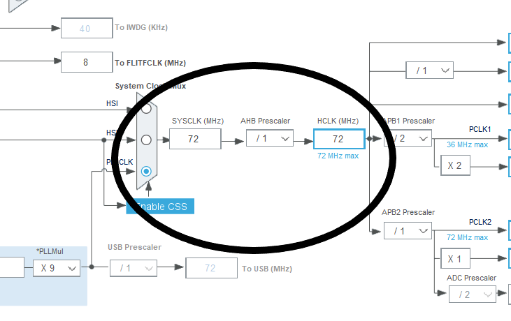
After configuration:
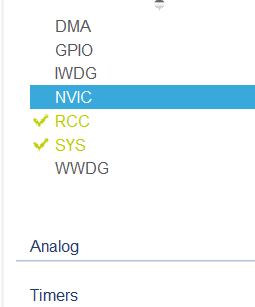
Note: after configuration, you can pay attention to the places shown in the figure below. If it is green, it means there is no problem. If it is yellow (warning) or red (error), it needs to be reconfigured and adjusted.
1.4 project export
Write out the required project name and saved address in the project Manager, as well as other configuration contents:
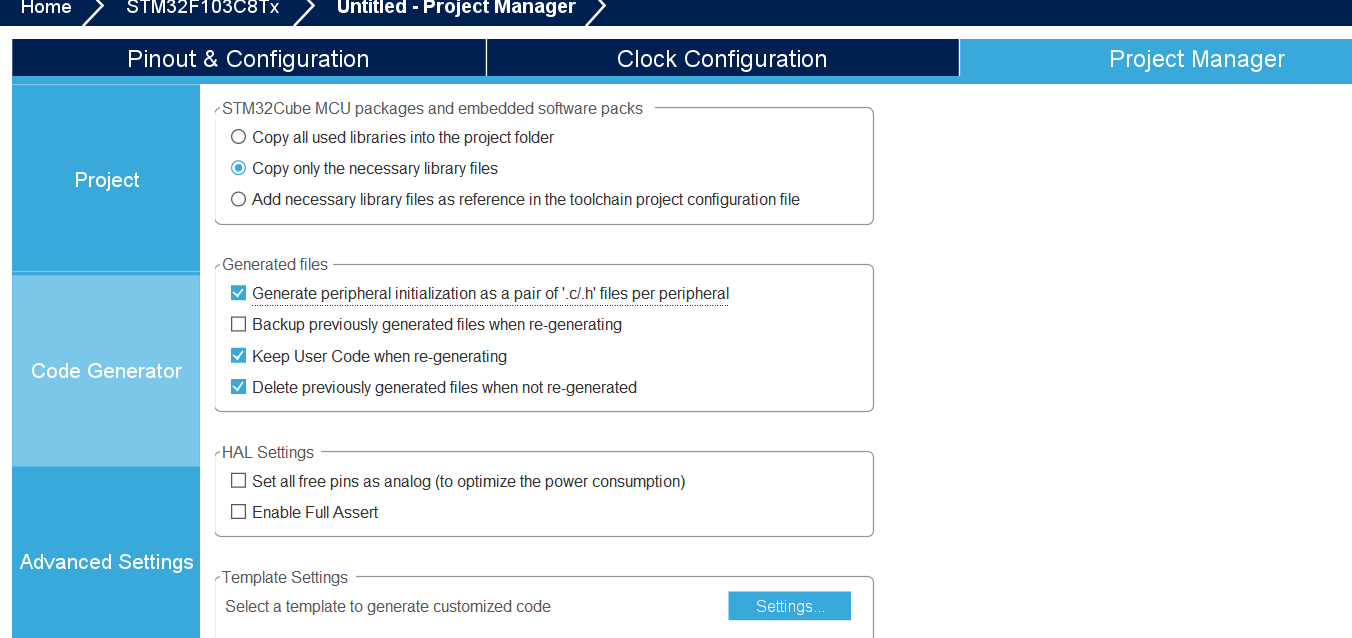
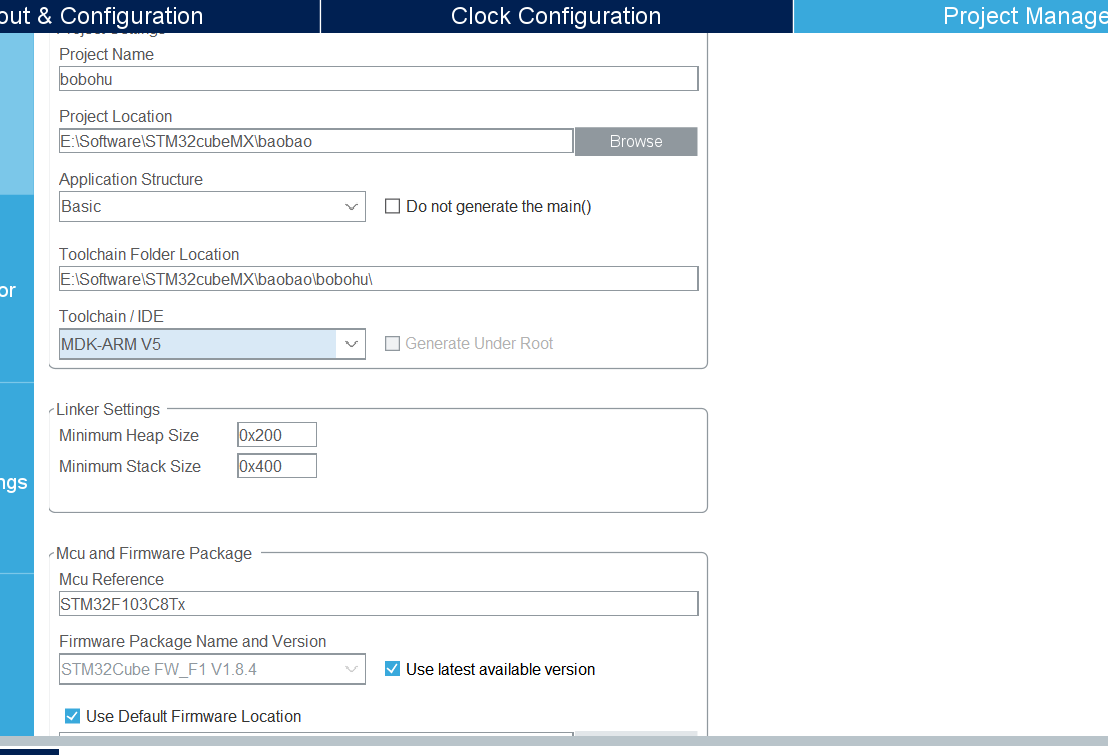
Then click GENERATE CODE Export project and generate keil project:

2, Improvement and Simulation in keil
2.1 improve functions
Find the path saved in stm32cubemx, find the keil file, and open it. You can see that there are already many files in the project:
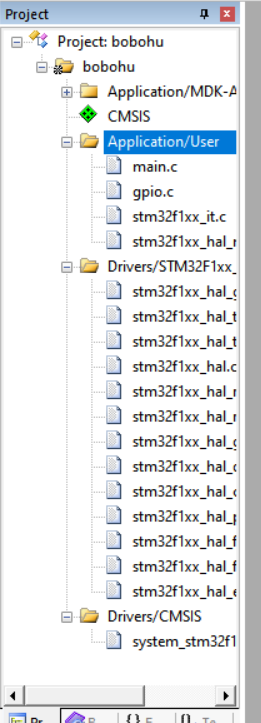
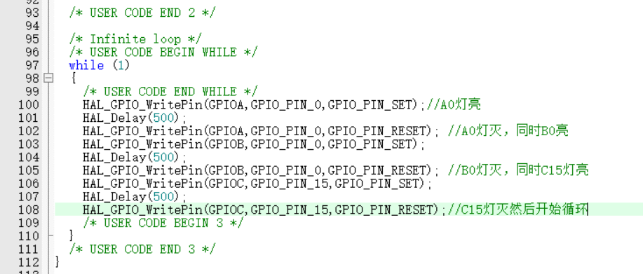
Find gpio.c and main.c, click to browse, and then add the following code to while in the main function:
		HAL_GPIO_WritePin(GPIOA,GPIO_PIN_0,GPIO_PIN_SET);//A0 light on
		HAL_Delay(500);
		HAL_GPIO_WritePin(GPIOA,GPIO_PIN_0,GPIO_PIN_RESET);	//A0 light is off and B0 is on
		HAL_GPIO_WritePin(GPIOB,GPIO_PIN_0,GPIO_PIN_SET);
		HAL_Delay(500);
		HAL_GPIO_WritePin(GPIOB,GPIO_PIN_0,GPIO_PIN_RESET);	//B0 light is off and C15 light is on
		HAL_GPIO_WritePin(GPIOC,GPIO_PIN_15,GPIO_PIN_SET);
		HAL_Delay(500);
		HAL_GPIO_WritePin(GPIOC,GPIO_PIN_15,GPIO_PIN_RESET);//The C15 light goes off and the cycle begins
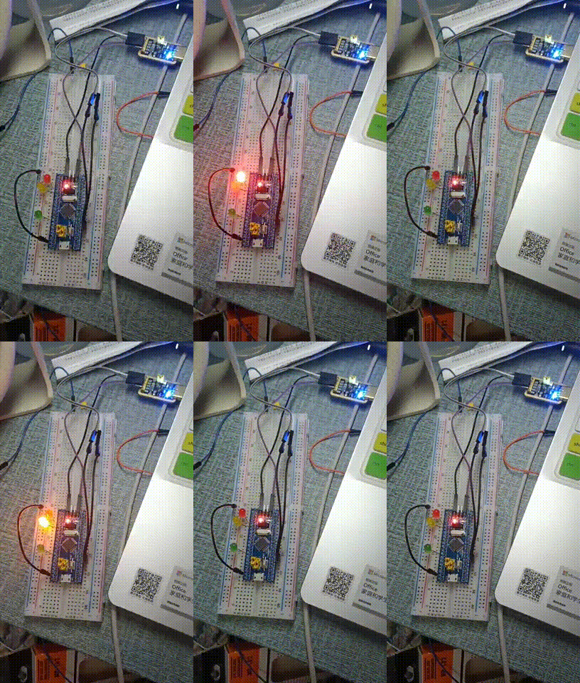
The results are shown in the figure below:
2.2 simulation waveform
As in the previous blog, first click the hammer, then click debug, and select use simulator to start the simulation
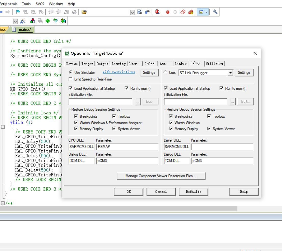
Then the logical window is added to add the pin number:

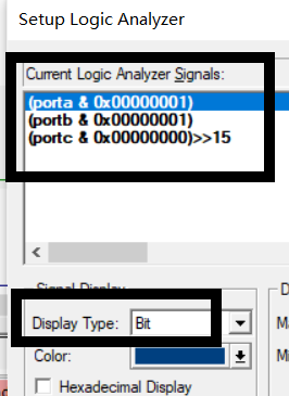
Start the simulation and get the waveform:

2.3 burning demonstration
Then you can burn. Connect the board to the computer and use FLYMCU to burn:
3, stm32usart serial communication
3.1 requirements:
(1) Set the baud rate to 115200, 1 stop bit and no check bit.
(2) STM32 system continuously sends "hello windows!" to the upper computer (win10), and the upper computer receiving program can use "serial port debugging assistant" or program itself.
(3) When the upper computer sends "Stop, stm32" to stm32, stm32 stops sending.
main.c
#include "stm32f10x.h"
void Delay_ms(volatile unsigned int t)
{
	unsigned int i,n;
	for(n=0;n<t;n++)
		for(i=0;i<800;i++);
}

void SysTick_Handler(void)
{
}


//Interrupt service function, previously in user_usart. C void user_usart_config (void) function
//USART_ITConfig(USART1, USART_IT_RXNE, ENABLE) enables the data reception interrupt, so
//The service interruption when receiving data will be handled
	int i=0;
	uint8_t a[11];
void USART1_IRQHandler(void)
{

	//uint8_t temp;


	if(USART_GetITStatus(USART1, USART_IT_RXNE) != RESET)
	{
		a[i++] = USART_ReceiveData(USART1);
		//USART_SendData(USART1, a[i-1]);


	}
	if(a[0]=='S'&&a[1]=='t'&&a[2]=='o'&&a[3]=='p'&&a[4]==','&&a[5]=='s'&&a[6]=='t'&&a[7]=='m'&&a[8]=='3'&&a[9]=='2')
		while(1);
}
void User_USART_Send_Byte(USART_TypeDef* pUSARTX, uint8_t Data)
{

	//Write 8bit data to the data register
	pUSARTX->DR = (Data & (uint16_t)0x01FF);

	//USART_GetFlagStatus checks whether the data is sent
	while(USART_GetFlagStatus(pUSARTX, USART_FLAG_TXE) == RESET);

}


//Send a string data to the serial port, that is, you can send data containing multiple bytes. The char type is 8bit. Each character in the string can be represented by an int number, that is, ASCII standard
void User_UART_Send_String(USART_TypeDef* pUSARTX, char* str)
{
  unsigned int i = 0;
	do
	{
		User_USART_Send_Byte(pUSARTX, *(str + i));
		i++;
	}
	while(*(str+i)!='\0');

		//USART_GetFlagStatus checks whether multiple data are sent
		while(USART_GetFlagStatus(USART1, USART_FLAG_TC) == RESET)


	{

}

int main(void)
{
	User_USART_GPIO_Config();
	User_NVIC_Config();
	User_USART_Config();

	User_UART_Send_String(USART1, "abcdefg!\n");

	while(1)
	{
     User_UART_Send_String(USART1, "hello windows!\n");
     Delay_ms(5000);
	}

}
3.2 burning
The modified program is simulated and burned into the chip (with FLYMCU)
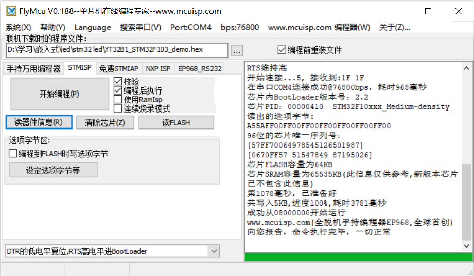
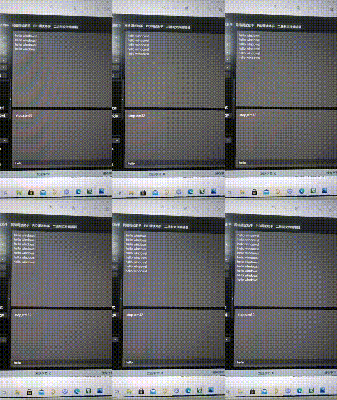
After running successfully, open the wildfire multi-functional debugging assistant to run (first download a compressed package, and then decompress it to run directly). Click to open the serial port, and you will find that the chip has been sending hello and window
4, Summary
Using stm32cubemx to directly generate projects is really convenient and saves us a lot of energy. Through this experiment, we can almost skillfully use stm32cubemx.
5, References
(53 messages) STM32USART serial communication _txmnqaqblog - CSDN blog
(53 messages) STM32 serial communication sends hello windows_eininbebop blog CSDN blog
(53 messages) USART serial communication _m0_47159351 blog of STM32 - CSDN blog