1) Experimental platform: new starting point V2 development board of punctual atom
2) Platform purchase address: https://detail.tmall.com/item.htm?id=609758951113
2) Full set of experimental source code + manual + video download address: http://www.openedv.com/thread-300792-1-1.html
3) Students interested in punctual atomic FPGA can add group discussion: 994244016
4) pay attention to the official account of the dot atom and get updated information.

Chapter 15 window dog (WWDG) experiment
Let's learn this chapter STM32MP1 Window watchdog( WWDG)We use the interrupt function of window watchdog to feed the dog and LED Light to observe dog feeding and reset.
This chapter will be divided into the following sections:
15.1 introduction to WWDG;
15.2 WWDG experiment;
15.1 WWDG introduction
15.1.1 STM32MP157 watchdog
- Introduction to watchdog
STM32MP157 has three watchdog, of which two independent watchdog (IWDG1 and IWDG2) are used by MPU and the other window watchdog (WWDG1) is used by MCU. IWDG watchdog has an independent clock and is driven by LSI. It can remain active even if the master clock fails. The clock of WWDG is driven by APB1 clock after frequency division, with a maximum of 104.5MHz.
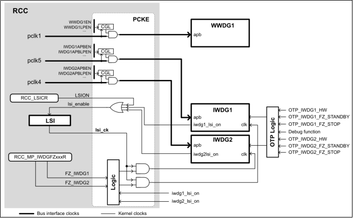
Figure 15.1.1.1 stm32mp157 watchdog resources
2. Window watchdog block diagram
Window watchdog (WWDG) and independent watchdog (IWDG1) Similarly, it is a decreasing counter. When the independent watchdog counter decreases to 0, it will reset. If you feed the dog before decreasing to 0, it will not reset. The window watchdog is different. When the window watchdog decreases to 0X40, if you do not feed the dog, it will reset at the next count of 0X3F. If you want to feed the dog, it should also be within a certain time range Feeding the dog will not lead to reset. We use a diagram to illustrate the working process of the window watchdog:
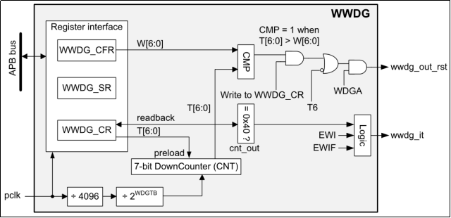
Figure 15.1.1.2 wwdg block diagram
From the block diagram of WWDG, we can know that WWDG has an input clock (clock pclk), which passes through a 4096 frequency divider and a frequency division coefficient (2 WDGTB) The programmable prescaler provides a clock to a 7-bit down counter later, and then the down counter starts to work. The down counter decreases one by one from the initial value according to this clock frequency, and a fixed clock cycle is used for each decline, so as to realize the down timing. Let's look at several signals in the block diagram, as shown in the following table:
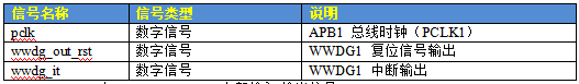
Table 15.1.1. 1 WWDG internal input / output signals
The block diagram is described as follows:
●pclk
The PCLK clock is provided by PCLK1 and can be up to 104.5MHz. The subsequent frequency division coefficient (2WDGTB) is configured by the user, so the clock frequency to WWDG = PCLK1/(40962WDGTB).
●T[6:0]
The lower 7 bits WWDG_CR[6:0] of the control register are used to decrement the count, that is, the counter T[6:0] in the figure. Its initial value can be configured by the user. These 7 bits can be configured as 1, which is the maximum initial value (0X7F). The time interval of each count of the decrement counter = (40962WDGTB)/ Fpclk. If you want to count N times, the time to be used is: n * (4096 * 2wdgtb) /Fpclk. The minimum decrement counter can be decremented to 0X3F.
●W[6:0]
The lower 7-bit WWDG_CFR[6:0] of the configuration register, that is, W[6:0] in the figure, is used to compare with the value of the lower 7-bit counter (T[6:0]) of the control register. The value of WWDG_CFR[6:0], that is, the upper limit value, is set by the user and cannot be set to 0X40. The maximum value can be set equal to the initial value of the decrement counter.
● T6 bit
It is the 6th bit of the control register, that is, the highest bit of the down counter T[6:0]. When the down counter decreases from 0X40 to 0X3F, a reset is generated, and the 6th bit changes from 1 to 0. 0X40 is the lower limit value of the window, which is fixed.
We use a diagram to illustrate the working process of WWDG:
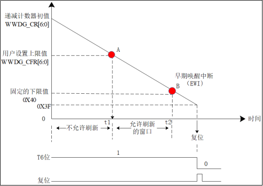
Figure 15.1.1.3 wwdg working diagram
In the above figure, the initial value of the decrement counter of the window watchdog is configured by the user, the upper limit value is determined by the user by setting the value of bit 06 of WWDG_CFR (point A), and the lower limit value is fixed, 0x40 (point B) Bit 06 of the register WWDG_CR is used to store the counter value of the watchdog. This value can be updated gradually. If the dog is fed before decreasing to A, the system will reset. If the dog is fed between A and B, the system will not reset. If the dog is not fed after decreasing to B, if the early wake-up interrupt is enabled, enter this interrupt. If there is no early wake-up interrupt Enable the wake-up interrupt in advance. When the counter is decremented to the next count 0X3F (i.e. the moment when T6 bit is 0), the system will reset. It is vividly called window, that is, the dog feeding time is A range (window) with upper and lower limits, and the dog feeding time can not be too early or too late.
(1) The window watchdog of STM32MP157 is reset under one of the following two conditions:
① When feeding dogs, if the value of the down counter is greater than the set value WWDG_CFR[6:0] (upper limit value);
② When the value of the down counter decreases from 0x40 to 0x3F (when the T6 bit jumps to 0).
(2) Here are some points to note:
① Dog feeding means clearing the decrement counter (reloading the counter value, also known as the refresh window) and allowing the timer to start decrement again.
② The upper window limit value must be greater than the lower window value 0x40 (the maximum can be set to 0X7F), otherwise the window watchdog will have no window.
③ The independent watchdog is not interrupted and the timeout is reset directly. The window watchdog is interrupted, such as the early wake-up interrupt (EWI) of the window watchdog , if the window watchdog is started and the early wake-up interrupt is allowed, the early wake-up interrupt will be triggered when the down counter is equal to 0x40. This interrupt can be used to feed the dog to avoid reset or do some function operations before reset, such as backing up important data, alarm prompt, etc.
④ Once the watchdog is enabled, WWDG cannot be disabled except for system reset.
(3) Timeout formula of window watchdog
Knowing the working principle of the window watchdog, let's learn how to calculate the timeout formula of the window watchdog. The timeout (or overflow time) here refers to how long it takes for the watchdog counter to decrease from the initial value to 0X3F, that is, the new time range of the WWDG counter (between the maximum value and the minimum value).
Of which:
TWWDG: WWDG timeout (unit: ms);
Fpclk1: clock frequency of APB1 (unit: Khz);
WDGTB[2:0]: the pre frequency division coefficient of WWDG. For user configuration, you can select 0 ~ 7. If 0 is selected, 20 = 1. If 7 is selected, 27 = 128.
T[5:0]: the lower 5 bits of the window watchdog counter are configured by the user. The minimum is 0x00 and the maximum is 0x3F. The larger the configuration, the longer the timeout.
According to the above formula, assuming Fpclk1=104.5Mhz, the minimum and maximum timeout can be obtained, as shown in the following table:
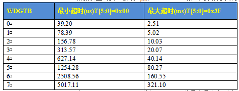
Table 15.1.1.2 minimum and maximum timeout of WWDG under 104.5mhz clock
Our later experimental parameters are set as follows:
PCLK1 is 104.5MHz; WDGTB=4; WWDG_CR[6:0] initial value = T[5:0]=0x3F; Window value WWDG_CFR[6:0]= W[6:0]=0X57. That is, the wdgtb frequency division coefficient is 4, the initial value of the timer is 128 and the window value is 95. Then the maximum timeout time is 40.14ms, the timer decreases one by one from 128, and the window value is 95, then the time corresponding to the window value is calculated as follows:
If the dog is fed between 0ms20.70ms after the watchdog runs, the system will reset. If the dog is fed between 20.70ms and 40.14ms after the watchdog runs, the system will not reset. If the dog is not fed after 40.14ms, the system will reset automatically.
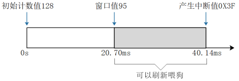
Figure 15.1.1.4 wwdg working diagram
3. Why WWDG
The window watchdog can check whether the program runs according to the predetermined logic, and can be used to detect system faults and software errors. The window threshold of refreshing the watchdog is set by calculating the normal running time of the program, which can ensure that the watchdog is refreshed within the specified time range. If the program flies, it is very difficult to feed the dog within the specified time range. If the program flies, the dog is not fed in time, the system resets, and we can detect that the program is abnormal.
4. MCU reset source
There are four possible reset sources for MCU: system reset, reset generated by MPU, WWDG1 reset (wwdg1_out_rst), and reset generated by MCU itself. WWDG1 takes APB1 clock as the clock and provides reset and early wake-up interrupt signals. This signal can be received by MPU (GIC) and MCU (NVIC) interrupt controller. In case of timeout (wwdg1_out_rst signal), WWDG1 will also reset MCU. If WWDG1 module resets MCU, this signal will also be routed to EXTI to wake up MPU core.
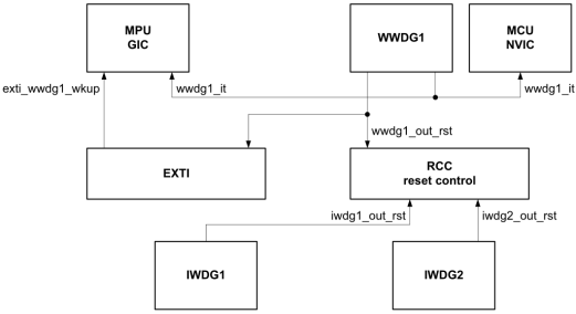
Figure 15.1.1.5 wwdg and MCU reset
15.1.2 WWDG register
WWDG register, we focus on the following three:
- Control register (WWDG_CR)
The control register of the window watchdog is described as follows:
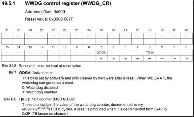
Figure 15.1.2.1 wwdg_ CR register
The register is only valid for the lower eight bits, in which T[6:0] is used to store the value of the watchdog counter, which is updated at any time every (4096) × 2^ WDGTB[2:0]) PCLK cycles minus 1. When the value of the counter changes from 0X40 to 0X3F, a watchdog reset will be generated.
WDGA bit is the activation bit of the watchdog. This bit is set to 1 by the software to start the watchdog. It must be noted that once this bit is set, it can only be cleared after hardware reset.
2. Configuration register (WWDG_CFR)
The configuration register is described as follows:
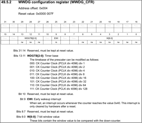
Figure 15.1.2.2 wwdg_ CFR register
The EWI bit in this register is an early wake-up interrupt. If this position is 1, an early wake-up interrupt is generated when the down counter is equal to 0x40, we can feed the dog in time to avoid WWDG reset, and the interrupt is cleared by the hardware only after reset. Therefore, we usually use this bit to set the interrupt. When the counter value of the window watchdog decreases to 0x40, if this bit is set and the interrupt is turned on, an interrupt will be generated. We can report to the WWDG in the interrupt_ CR writes the counter value again to feed the dog. Note that after entering the interrupt, the WWDG must be rewritten within a time of no more than one window watchdog counting cycle (34.13us under the condition that pclk3 frequency is 120M and WDGTB[2:0] is 0)_ Cr, otherwise, the watchdog will generate reset!
W[6:0] is a 7-bit window value containing the window value used for comparison with the down counter.
WDGTB[2:0] is the timer time base. The time base of prescaler can be modified as follows:
000: CK counter clock (PCLK div 4096) divider 1
001: CK counter clock (PCLK div 4096) divider 2
010: CK counter clock (PCLK div 4096) divider 4
011: CK counter clock (PCLK div 4096) divider 8
100: CK counter clock (PCLK div 4096) divider 16
101: CK counter clock (PCLK div 4096) divider 32
110: CK counter clock (PCLK div 4096) divider 64
111: CK counter clock (PCLK div 4096) divider 128
3. Status register (WWDG_SR)
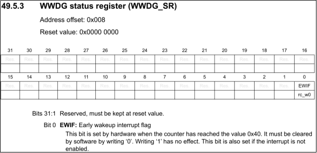
Figure 15.1.2.3 wwdg_ SR register
This register is used to record whether there is an early wake-up flag. Only bit 0 of this register is valid, and the others are reserved bits. When the counter value reaches 0x40, this bit is set to 1 by hardware. It must be cleared by software writing 0. Writing 1 to this bit is not valid. Even if the interrupt is not enabled, this bit will be set to 1 when the counter value reaches 0x40.
4. Clock enable register
In addition, if you want to use WWDG, you have to enable the clock of WWDG. WWDG is hung on APB1, so you need to configure register RCC_ MC_ In the 28th bit of apb1ensetr, set it to 1 to start the WWDG clock. In later experiments, the initialization code generated by stm32cube ide will automatically do this step for us.
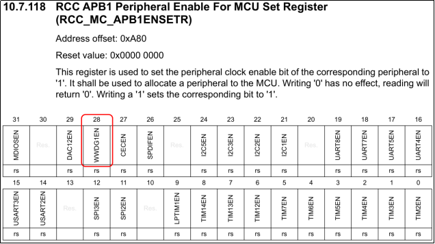
Figure 15.1.2.4 RCC_ MC_ Apb1ensetr register
5. Other registers
In addition to the above important registers, there are:
Wwdg hardware configuration register (wwdg(u hwcfgr) is used to configure the watchdog clock prescaled to 4096; Wwdg Version Registration Register (WWDG_VERR) is used to record the main revision information of IP version; WWDG_SIDR and WWDG ID registers. We can't use these registers. We can ignore them.
15.1.3 HAL library drive of wwdg
The HAL library driver code of WWDG is in stm32mp1xx_hal_wwdg.c and stm32mp1xx_hal_wwdg.h file.
- Structures and handles
(1)WWDG_InitTypeDef structure
WWDG_InitTypeDef structure in stm32mp1xx_ hal_ Defined in wwdg. H file, it is mainly used to configure the frequency division value, window value, initial value of decrement counter of wwdg and whether to enable early wake-up interrupt. The initialization configuration of these parameters of wwdg can be completed by assigning a value to this structure member.
typedef struct
{
  uint32_t Prescaler;  					/* Specifies the prescaler value for the WWDG */
/* Specifies the WWDG window value to compare with the decrement counter, which must be between the numbers 0x40 and 0x7F */
  uint32_t Window;
/* Specifies the initial value of the WWDG decrement counter, which must be a number between 0x40 and 0x7F */
  uint32_t Counter;
/* Specifies whether to use an early wake interrupt */
  uint32_t EWIMode ;
} WWDG_InitTypeDef;
(2)WWDG_TypeDef
WWDG_TypeDef structure in stm32mp157axx_cm4.h file defines the offset address of wwdg register. As we have emphasized many times before, the registers of peripherals are in stm32mp157axx_cm4.h file is encapsulated by structure. Wwdg involves few registers, as follows:
typedef struct
{
  __IO uint32_t CR;      			/* WWDG Control register, address offset: 0x00 */
  __IO uint32_t CFR;     			/* WWDG Configuration register, address offset: 0x04 */
  __IO uint32_t SR;      			/* WWDG Status register, address offset: 0x08 */
  uint32_t  RESERVED1[249];   	/* Reserved, 0x0C-0x3EC */
  __IO uint32_t HWCFGR; 			/* WWDG Hardware configuration register, address offset: 0x3F0 */
  __IO uint32_t VERR;    			/* WWDG Version register, address offset: 0x3F4 */
  __IO uint32_t IPIDR;   			/* WWDG Identification register, address offset: 0x3F8 */
  __IO uint32_t SIDR;    			/* WWDG Size ID register, address offset: 0x3FC */
} WWDG_TypeDef;
(3)WWDG_HandleTypeDef handle definition
WWDG_HandleTypeDef handle in stm32mp1xx_ HAL_ It is defined in wwdg. H file. The HAL library operates peripherals through handle operation.
#if (USE_HAL_WWDG_REGISTER_CALLBACKS == 1)
typedef struct __WWDG_HandleTypeDef
#else
typedef struct
#endif
{
  WWDG_TypeDef  *Instance;  				/* Register base address */
  WWDG_InitTypeDef  Init;   				/* WWDG Required parameters */
#if (USE_HAL_WWDG_REGISTER_CALLBACKS == 1)
/* WWDG Early wake-up interrupt callback function */
  void (* EwiCallback)(struct __WWDG_HandleTypeDef *hwwdg);
/* WWDG Msp Initialize callback function */
  void (* MspInitCallback)(struct __WWDG_HandleTypeDef *hwwdg);
#endif
} WWDG_HandleTypeDef;
	Let me mention it here USE_HAL_WWDG_REGISTER_CALLBACKS This macro is defined as 0 by default. In stm32mp1xx_hal_conf.h Defined in the file.
/* This is a list of modules that can use register callbacks */
#define USE_HAL_ADC_REGISTER_CALLBACKS    0u
#define USE_HAL_CEC_REGISTER_CALLBACKS    0u
#define USE_HAL_DAC_REGISTER_CALLBACKS    0u
#define USE_HAL_I2C_REGISTER_CALLBACKS    0u
#define USE_HAL_RNG_REGISTER_CALLBACKS    0u
#define USE_HAL_SPI_REGISTER_CALLBACKS    0u
#define USE_HAL_UART_REGISTER_CALLBACKS   0u
#define USE_HAL_USART_REGISTER_CALLBACKS  0u
#define USE_HAL_WWDG_REGISTER_CALLBACKS   0u
If these macros are defined as 0, they are used by default HAL Callback functions in the library, HAL The default callback functions in the library are basically weakly defined, so users can redefine a callback function with the same name. If these macros are defined as 1, the user can register the callback function himself, and the original weakly defined callback function is replaced by the callback function registered by the user. User registration WWDG Callback function part stm32mp1xx_hal_wwdg.h There are in the document, as follows:
#if (USE_HAL_WWDG_REGISTER_CALLBACKS == 1)
/**
  * @brief  Register the user WWDG callback function instead of the weak predefined callback function
  * @param  hwwdg: WWDG handle
  * @param  CallbackID: The ID of the callback to register. This parameter can be one of the following values
  *           @arg @ref HAL_WWDG_EWI_CB_ID: Early wake interrupt callback ID
  *           @arg @ref HAL_WWDG_MSPINIT_CB_ID : MspInit Callback ID
  * @param pCallback: Pointer to callback function
  * @retval state
  */
HAL_StatusTypeDef HAL_WWDG_RegisterCallback(WWDG_HandleTypeDef *hwwdg, HAL_WWDG_CallbackIDTypeDef CallbackID, pWWDG_CallbackTypeDef pCallback)
{
  HAL_StatusTypeDef status = HAL_OK;
  if(pCallback == NULL)
  {
    status = HAL_ERROR;
  }
  else
  {
    switch(CallbackID)
    {
      case HAL_WWDG_EWI_CB_ID:
        hwwdg->EwiCallback = pCallback;
        break;
      case HAL_WWDG_MSPINIT_CB_ID:
        hwwdg->MspInitCallback = pCallback;
        break;
      default:
        status = HAL_ERROR;
        break;
    }
  }

  return status;

```c
}

/**
- @brief unregisters the WWDG callback function, and the WWDG callback is redirected to the weak (charging) predefined callback function.
- @param hwwdg: WWDG handle
- @Param callback ID: the ID of the callback to be registered. This parameter can be one of the following values
-
@arg @ref HAL_WWDG_EWI_CB_ID: Early wake-up interrupt callback ID
-
@arg @ref HAL_WWDG_MSPINIT_CB_ID : MspInit Callback ID
- @retval status
*/
HAL_StatusTypeDef HAL_WWDG_UnRegisterCallback(WWDG_HandleTypeDef *hwwdg, HAL_WWDG_CallbackIDTypeDef CallbackID)
{
HAL_StatusTypeDef status = HAL_OK;
switch(CallbackID)
{
case HAL_WWDG_EWI_CB_ID:
hwwdg->EwiCallback = HAL_WWDG_EarlyWakeupCallback;
break;
case HAL_WWDG_MSPINIT_CB_ID:
hwwdg->MspInitCallback = HAL_WWDG_MspInit;
break;
default:
status = HAL_ERROR;
break;
}
return status;
}
#endif
	among HAL_WWDG_RegisterCallback Is the code used to register the callback function specified by the user. Let's focus on two lines of red code, pCallback Is a pointer to a user-defined callback function. The code of this function is through CallbackID To register or specify user-defined WWDG Early wake-up interrupt callback function and MspInit Callback function, HAL The weakly defined callback function in the library is not used (or replaced by the user specified callback function).
	HAL_WWDG_UnRegisterCallback The function means to cancel the registration. We also look at the above two lines of code marked in red. The function pointer points to HAL The callback function in the library, that is, using HAL The callback function in the library does not use the user-defined callback function. Deregistration is to unregister the user-defined callback function.
	Our later experiments use it by default HAL The callback function is weakly defined in the library. You can customize the callback function if you want. Let's take a look HAL In Library API Function.
2. HAL In Library API function
(1)HAL_WWDG_Init
●Function function: HAL_WWDG_Init Function based on the WWDG_InitTypeDef To initialize WWDG.
●Function parameters:
	hwwdg: point WWDG_HandleTypeDef Pointer to the structure that contains the specified WWDG Configuration information for.
●Function return value: enumeration type, HAL_OK(success),HAL_ERROR(Error) HAL_BUSY(Serial port busy) HAL_TIMEOUT((timeout)

```c
1   HAL_StatusTypeDef HAL_WWDG_Init(WWDG_HandleTypeDef *hwwdg)
2   {
3     /* Check WWDG handle allocation */
4     if (hwwdg == NULL)
5     {
6       return HAL_ERROR;
7     }
8     /* Check parameters */
9     assert_param(IS_WWDG_ALL_INSTANCE(hwwdg->Instance));
10    assert_param(IS_WWDG_PRESCALER(hwwdg->Init.Prescaler));
11    assert_param(IS_WWDG_WINDOW(hwwdg->Init.Window));
12    assert_param(IS_WWDG_COUNTER(hwwdg->Init.Counter));
13    assert_param(IS_WWDG_EWI_MODE(hwwdg->Init.EWIMode));
14
15  #if (USE_HAL_WWDG_REGISTER_CALLBACKS == 1)
16    /* Reset callback pointer */
17    if(hwwdg->EwiCallback == NULL)
18    {
19      hwwdg->EwiCallback = HAL_WWDG_EarlyWakeupCallback;
20    }
21    if(hwwdg->MspInitCallback == NULL)
22    {
23      hwwdg->MspInitCallback = HAL_WWDG_MspInit;
24    }
25    /* Initialize underlying hardware */
26    hwwdg->MspInitCallback(hwwdg);
27  #else
28    /* Initialize underlying hardware */
29    HAL_WWDG_MspInit(hwwdg);
30  #endif
31    /* Set WWDG counter value */
32    WRITE_REG(hwwdg->Instance->CR, (WWDG_CR_WDGA | 																		hwwdg->Init.Counter));
33    /* Set up WWDG prescaler and window */
34    WRITE_REG(hwwdg->Instance->CFR, (hwwdg->Init.EWIMode | 									hwwdg->Init.Prescaler | hwwdg->Init.Window));
35    /* Return to function status */
36    return HAL_OK;
37  }
(
2)HAL_WWDG_Refresh
● function function: refresh WWDG
● function parameters:
hwwdg: point to WWDG_ Pointer to the handletypedef structure, which contains the configuration information of the specified WWDG.
● function return value: enumeration type, Hal_ OK, HAL_ERROR, HAL_BUSY, HAL_TIMEOUT
HAL_StatusTypeDef HAL_WWDG_Refresh(WWDG_HandleTypeDef hwwdg)
{
/Writes the WWDG counter value to the WWDG CR register to refresh*/
WRITE_REG(hwwdg->Instance->CR, (hwwdg->Init.Counter));
return HAL_OK;
}
HAL_ WWDG_ The refresh function is simple and calls write_ The reg function assigns the initial value of the counter set in the handle to the wwdg_ The lower 6 bits of the CR register to realize the refresh timer.
(3)HAL_WWDG_IRQHandler function
● function function: processing WWDG interrupt request
● function parameters:
hwwdg: point to WWDG_ Pointer to the handletypedef structure, which contains the configuration information of the specified WWDG.
● function return value: enumeration type, Hal_ OK, HAL_ERROR, HAL_BUSY, HAL_TIMEOUT
● note: if the early wake-up interrupt is enabled, the early wake-up interrupt can be generated when the down counter reaches the value 0x40. If a specific safety operation or data recording must be performed before the actual reset is generated, the early wake-up interrupt (EWI) can be used
1   void HAL_WWDG_IRQHandler(WWDG_HandleTypeDef *hwwdg)
2   {
3     /* Check whether the early wake-up interrupt is enabled */
4     if (__HAL_WWDG_GET_IT_SOURCE(hwwdg, WWDG_IT_EWI) != RESET)
5     {
6       /* Check whether WWDG early wake-up interrupt has occurred */
7       if (__HAL_WWDG_GET_FLAG(hwwdg, WWDG_FLAG_EWIF) != RESET)
8       {
9         /* Clear WWDG wake in advance flag */
10        __HAL_WWDG_CLEAR_FLAG(hwwdg, WWDG_FLAG_EWIF);
11
12  #if (USE_HAL_WWDG_REGISTER_CALLBACKS == 1)
13        /* Wake up early registration callback function */
14        hwwdg->EwiCallback(hwwdg);
15  #else
16        /* Early wake-up callback function */
17        HAL_WWDG_EarlyWakeupCallback(hwwdg);
18  #endif
19      }
20    }
21  }
HAL_WWDG_IRQHandler The interrupt request function is also relatively simple.
Line 4, the program reads WWDG_CFR Register EWI Bit to determine whether the early wake-up interrupt has been enabled. If the early wake-up interrupt has been enabled, read through line 7 WWDG_SR Early wake interrupt flag of register EWIF To determine whether there is an early wake-up interrupt. If there is an early wake-up interrupt, clear the early wake-up interrupt first and call the early wake-up interrupt callback function for corresponding processing. In the chapter of external interrupt experiment, we said that after an interrupt occurs, remember to clear the interrupt flag bit after entering the interrupt processing function. If it is not cleared, it will cause the program to re-enter the interrupt after executing the callback function, resulting in the program card being in the interrupt and unable to return to the main function.
twelfth~18 Line. If the user has a custom callback function, the user-defined early wake-up interrupt callback function will be executed. If the user does not have a custom callback function, it will be executed by default HAL Callback function in library.
(4) Other functions
In addition, there is HAL_WWDG_MspInit initialization function and HAL_WWDG_EarlyWakeupCallback wakes up the interrupt callback function in advance. Both functions are weakly defined. Stm32cube ide will automatically generate a new Hal for us_ WWDG_ Mspinit function, used to enable HSEM and set interrupt priority grouping. And Hal_ WWDG_ The code of the earlywakeupcallback function needs to be implemented manually.
15.2 WWDG test
15.2.1 hardware design
- Routine function
Start the early wake-up interrupt in the program, and automatically feed the dog in the callback function. After the program runs, light LED0 for 100ms, initialize WWDG, and then turn LED0 off. LED1 will turn over when feeding dogs, and LED0 will be lit again when MCU reset occurs. We observe whether feeding the dog is interrupted by turning the LED1 lamp. - hardware resource
1) LED:
LED0 LED1 bus
PI0 PF3 AHB4
Table 15.2.1.1 hardware resources
2) Window watchdog: located on APB1 bus. - schematic diagram
The window watchdog belongs to the internal resource of STM32MP157. It can work normally only after the software is set. We use LED0 and LED1 to indicate the reset of STM32MP157 and the dog feeding of window watchdog.
15.2.2 software design
The experimental project configured for this experiment has been placed on the development board CD. The path is: development board CD A - basic data \ 1, program source code \ 11, M4 CubeIDE bare metal driver routine \ CubeIDE_project\ 8 WWDG. - Program flow chart
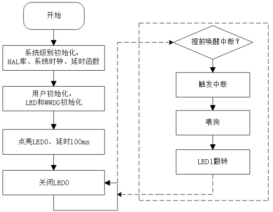
Figure 15.2.2.1 procedure flow chart
2. Generate project
(1) Configure LED pin
According to the running lamp experiment, PI0 and PF3 are configured as push-pull output, pull-up and high-speed modes. The User Label remains the same as the previous settings, because we will use the led.h and led.c files of the previous experiment later. Of course, you can also directly configure WWDG in the running lantern experiment project, saving the trouble of re creating the project.
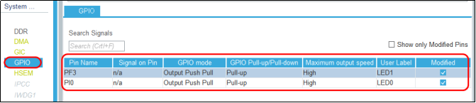
Figure 15.2.2.2 configuring LED pins
(2) Configure WWDG
Open the System CoreWWDG1 on the left and configure the WWDG parameters. We will configure the WDGTB frequency division value as 16, the initial value of the timer as 128 and the window value as 95 according to the above, and enable early wake-up interrupt.
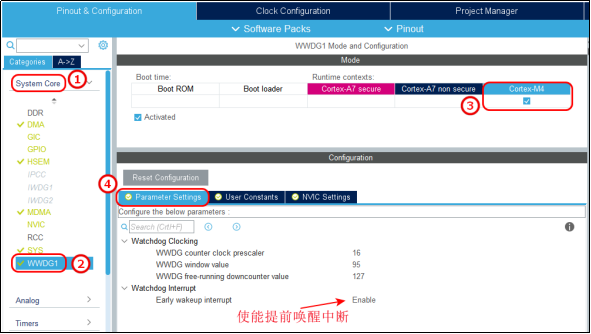
Figure 15.2.2.3 configuring WWDG parameters
Enable watchdog interrupt at NVIC Settings. At this time, interrupt preemption priority and sub priority are both 0:
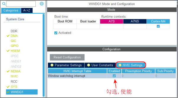
Figure 15.2.2.4 enable WWDG interrupt
0 has the highest priority, and the priority of system level interrupts and tick timer interrupts is also 0. Therefore, we configure watchdog interrupt priority at NVIC settings, set interrupt priority group to 2, preemption priority and sub priority to 3, and set it to other priority levels. We have analyzed it in the previous chapter of external interrupt experiment.
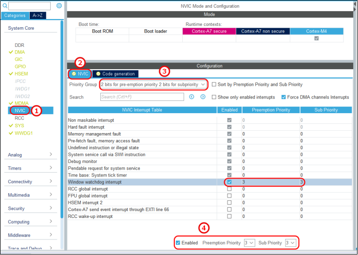
Figure 15.2.2.5 configuring WWDG interrupt priority
(3) Clock and engineering configuration
If the clock is used, we can configure PCLK1 as 104.5MHz, either an internal clock or an external clock. If the external clock is used, we can refer to the previous clock system chapter for configuration. Here we use the default HSI, and the configuration is as follows:
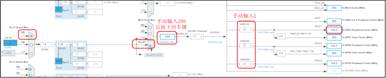
Figure 15.2.2.6 configure PCLK1 clock to 104.5MHz
After configuring the clock, return to the Project Manager configuration interface and check the Generate peripheral initialization as a pair of ".c/.h'files per peripheral option, so that the initialization. h and. c files of corresponding peripherals can be generated independently (this is also to prevent the initialization code of peripherals from being generated in the main.c file for easy viewing and avoid the main.c file becoming bloated):
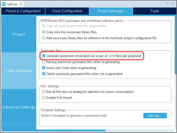
Figure 15.2.2.7 configuration generates independent initialization code
(4) Generate initialization code
Press "Ctrl+S" to save the configuration and generate the project. As shown in the following figure, you can see that there is an additional gpio.c file and wwdg.c file in the project. gpio.c file is introduced earlier, mainly to complete the initialization of gpio. wwdg.c is mainly to complete the initialization of WWDG.
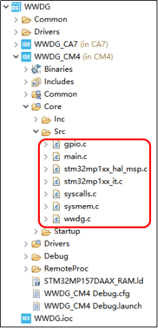
Figure 15.2.2.8 generation engineering
3. Add user code
(1) Add running light driver
Copy the BSP folder created by the running lantern experiment to the Src folder, as shown in the following figure:
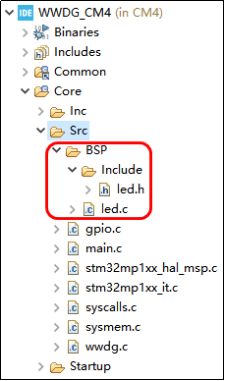
Figure 15.2.2.9 adding LED initialization code
(2) Add the following code in main.c:
led_init(); / * turn off LED0 and LED1/
LED0(0); / open LED0/
HAL_Delay(100);
/Add the following code to the while loop/
LED0(1); / close LED0*/
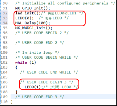
Figure 15.2.2. 10 adding logic code to main. C
(3) Add the following code to the led.c.c file
#include "./Include/led.h"
#include "wwdg.h"
void led_init(void)
{
    LED0(1);    		/* Close LED0 */
    LED1(1);   		 	/* Close LED1 */
}
/**
 * @brief       Window watchdog interrupt service callback function
 * @param       nothing
 * @note        This function is called by HAL_WWDG_IRQHandler()
 * @retval      nothing
 */
void HAL_WWDG_EarlyWakeupCallback(WWDG_HandleTypeDef *hwwdg)
{
    HAL_WWDG_Refresh(&hwwdg1);	/* Refresh window watchdog value */
    LED1_TOGGLE();					/* LED1 Lamp flip */
}
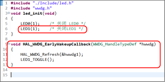
Figure 15.2.2. 11 user defined callback function
In the led_init function, first turn LED1 off. We add code to test the phenomenon, and then we analyze the code.
4. Compilation and testing
After saving the changes, click the small hammer on the toolbar to compile. After the compilation has no error, connect the development board and St link according to section 4.1.6 and enter the Debug mode. After entering the Debug, click the continue operation button to run the debugging. You can see that the LED0 light on the bottom plate of the development board goes out first, and then LED1 keeps flashing, indicating that the program is feeding the dog.
5. Engineering code analysis
We won't analyze the gpio.c file. Let's take a look at other files:
(1) wwdg.c file
wwdg.c The contents of the document are as follows:
1   /**
2    * @brief    Initialize window watchdog
3    * @note     fprer:Frequency division coefficient (WDGTB), range: 0 ~ 7, indicating 2^WDGTB frequency division
4    *           Fwwdg=PCLK1(APB1)/(4096*2^fprer). General PCLK1=104.5Mhz
5    *           Overflow time = (4096*2^fprer)*(T[6:0]-0X3F)/PCLK1
6    *           Suppose fprer=4,T[6:0]=0X7f,W[6:0]=0X5F, PCLK1=104.5Mhz
7    *           Overflow time = 4096*16*64/104.5Mhz=40.14ms
8    * @retval   nothing
9    */
10  #include "wwdg.h"
11
12  WWDG_HandleTypeDef hwwdg1;						/* Window watchdog handle */
13
14  /* WWDG1 Initialization function */
15  void MX_WWDG1_Init(void)
16  {
17    hwwdg1.Instance = WWDG1;						/* Operation WWDG1 */
18    hwwdg1.Init.Prescaler = WWDG_PRESCALER_16;	/* Set frequency division coefficient WDGTB */
19    hwwdg1.Init.Window = 95;						/* Set window value */
20    hwwdg1.Init.Counter = 127;						/* Set counter value */
21    /* Enable window watchdog early wake-up interrupt */
22    hwwdg1.Init.EWIMode = WWDG_EWI_ENABLE;
23    if (HAL_WWDG_Init(&hwwdg1) != HAL_OK)		/* Initialize WWDG */
24    {
25      Error_Handler();
26    }
27
28  }
29  /**
30   * @brief       WWDG Bottom drive
31   * @param       wwdgHandle:Window watchdog handle
32   * @note        This function is called by HAL_WWDG_Init()
33   * @retval      nothing
34   */
35  void HAL_WWDG_MspInit(WWDG_HandleTypeDef* wwdgHandle)
36  {
37    if(wwdgHandle->Instance==WWDG1)
38    {
39      /* WWDG1 Clock enable */
40      __HAL_RCC_WWDG1_CLK_ENABLE();
41      /* WWDG1 Interrupt priority initialization */
42      HAL_NVIC_SetPriority(WWDG1_IRQn, 3, 3);
43      /* WWDG1 Interrupt enable */
44      HAL_NVIC_EnableIRQ(WWDG1_IRQn);
45    }
46  }
Line 12, define a handle hwwdg1;
Lines 17 to 22 assign the set window value, frequency division coefficient WDGTB, initial counter value and early wake-up interrupt enable to the handle hwwdg1;
In lines 23 to 26, WWDG initialization is realized through handle assignment. After initialization, the window value of WWDG is 95, the frequency division coefficient WDGTB is 4, and the initial value of counter is 128.
In line 40, turn on the WWDG clock. The WWDG is hung on the APB1 bus. Turn on the WWDG clock by setting the 28th bit WWDG1EN of the APB1 external enable register RCC_MC_APB1ENSETR to 1.
In lines 42 to 44, set the preemptive priority and sub priority of WWDG to 3 and enable WWDG. WWDG1_IRQn is an interrupt number, which is defined in stm32mp157dxx_cm4.h file. We have talked about the relationship between interrupt number, interrupt vector table and interrupt service function many times before, so we won't explain it here.
(2) stm32mp1xx_hal_msp.c file
There is a HAL_MspInit function under stm32mp1xx_hal_msp.c file, which mainly enables HSEM and sets the interrupt priority group to 2. HAL_MspInit function will be called by HAL_Init function to complete the initialization of HAL library.
#include "main.h"
/* Initialize global MSP */
void HAL_MspInit(void)
{
/* Turn on HSEMEN peripheral clock */
  __HAL_RCC_HSEM_CLK_ENABLE();
/* Set the interrupt priority group to 2 */
  HAL_NVIC_SetPriorityGrouping(NVIC_PRIORITYGROUP_2);
}
(3)stm32mp1xx_it.c file
	stm32mp1xx_it.c We have also introduced the document many times before. Only and are posted here WWDG Relevant codes:
/* Interrupt service function */
void WWDG1_IRQHandler(void)
{
/*Interrupt request function */
  HAL_WWDG_IRQHandler(&hwwdg1);
}
In front of the API function analysis part, we introduced this function. Interrupt service function calls interrupt request function to complete the interrupt, and the interrupt request function calls the callback function HAL_WWDG_EarlyWakeupCallback. This callback function uses the default weak definite function in the HAL library. We need to define a callback function to handle the interruption.
(4) led.c file
The led.c file is copied from the previous running lamp experiment. We define the callback function Hal in the led.c file_ WWDG_ Earlywakeupcallback to refresh the counter (feed the dog). Of course, the callback function can also be defined in other places. That is, when the decrement counter decrements from the initial value 128 to 0X40 (hexadecimal 64), an early wake-up interrupt occurs. We feed the dog in the interrupt, so the system will not reset. LED1 will flip every time we feed the dog. Whenever the counter decreases from 128 to 64, LED1 flips once, and then the interrupt refreshes the counter. The counter decreases again from 128, and when it decreases to 64, it starts feeding the dog again. When the counter decreases from 128 to 64, 40.14ms has passed. This time is very short, isn't it? So you will find that LED1 light is turning frequently. If the program design has defects and runs away, it is still difficult to feed the dog in such a short time, so the window watchdog is often used to detect system defects.
(5) main.c file
	main.c The clock initialization code of the file has been analyzed in the previous clock system chapter, so it will not be pasted here.
1   #include "main.h"
2   #include "wwdg.h"
3   #include "gpio.h"
4
5   /* USER CODE BEGIN Includes */
6   #include "./BSP/Include/led.h"
7   /* USER CODE END Includes */
8
9   void SystemClock_Config(void);
10
11  int main(void)
12  {
13    HAL_Init();
14
15    if(IS_ENGINEERING_BOOT_MODE())
16    {
17      /* Initialize system clock */
18      SystemClock_Config();
19    }
20
21    /* Initialize the configured GPIO */
22    MX_GPIO_Init();
23    led_init();				/* Close LED0 and LED1 */
24    LED0(0);  				/* Open LED0 */
25    HAL_Delay(100);			/* Delay 100ms first and then open WWDG to make the change of LED0 "visible" */
26    MX_WWDG1_Init();		/* Initialize WWDG */
27    /* USER CODE BEGIN 2 */
28
29    while (1)
30    {
31      /* USER CODE BEGIN 3 */
32        LED0(1);				/* Close LED0 */
33    }
34    /* USER CODE END 3 */
35  }
main.c The code is relatively simple, that is, close it first LED1,Reopen LED0,Then initialize WWDG,Again in while In the loop LED0 close. So in the experiment, LED0 It is lit first. When the program enters the main function LED0 It turns off, and then there is an early wake-up interrupt. During the interrupt, the dog will be fed, and then you can see LED1 Flashing.