Experimental requirements: build the circuit with STM32 minimum system core board (STM32F103C8T6) + panel board + 3 red, green and blue LEDs, use GPIOB, GPIOC and GPIOD to control the LED lights, flash in turn, and the interval is 1 second. 1) Write the program design idea, including the register address and detailed parameters of GPIOx port; 2) It is programmed with assembly language and C language.
catalogue
2. Three steps for initialization and setting of GPIO port
5. Compile to generate HEX file
1, Experimental principle
1. Register mapping
Each register occupies 32 bits. The initial content of register operation is to find the starting address of the register. This step can be completed by searching the data manual, so how to use this manual?
You know, the mapping address of the register is divided into three steps. First, find the base address of the GPIOB, then find the address offset of the port input register, and finally find the corresponding port input data.
2. Three steps for initialization and setting of GPIO port
(1) Clock configuration
In order to reduce power consumption, first configure the clock enable. The information of the configured clock can be obtained by referring to the manual (name of clock control) The word is called RCC).
In order to configure the clock enable, first know the address of the clock enable register, then look up the manual and assign the bit of the corresponding function to 1, that is, turn on the GPIOB clock
(2) Input / output mode setting
In order to output high level and low level, the LED water lamp needs to be configured as output. Find the address of the corresponding register through From the reading materials, we can know that there are four modes of register output. According to the function of LED water lamp, it is set as general Push-pull output (it can output high and low levels and connect digital devices; push-pull structure generally refers to that two triodes receive two complementary signals respectively No. is always controlled when one triode is on and the other is off. The high and low levels are determined by the power supply of the IC.)
(3) Maximum rate setting
For STM32F103 series chips, the fastest configuration is 50Mhz, but the speed is not the faster the better. The higher the speed configuration, the greater the noise and the greater the power consumption, so the appropriate speed should be configured here.
3. Design ideas
The design idea of water lamp is: control register output 1, turn on the LED lamp, after a period of time, control the LED lamp off, and then add a circular statement to show the effect of water lamp.
2, Experimental steps
According to the above experimental principles, start the formal experiment.
1. Understanding registers
(1) GPIO register
Here we use GPIO registers, which can be divided into many classes according to function:
Each GPIO port has two 32-bit configuration registers (GPIOx_CRL,GPIOx_CRH, also known as control registers),
Two 32-bit data registers (GPIOx_IDR,GPIOx_ODR),
A 32-bit / reset register (GPIOx_BSRR),
A 16 bit reset register (GPIOx_BRR) and a 32-bit lock register (GPIOx_LCKR).
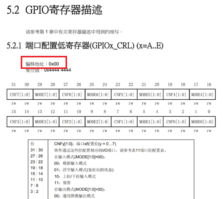
Here we use the port configuration low register (GPIOx_CRL)
(2)GPIO_CRL
The CRL of STM32 controls the low 8-bit MODE of each IO port (A-G). The bits of each IO port occupy 4 bits of the CRL. The high two bits are CNF and the low two bits are MODE. In fact, the role of CRH is exactly the same as that of CRL, except that CRH controls the high 8 bits and CRL controls the low 8 bits.
2. Find register address
In order to configure the port of the register and realize various functions, we need to find the address of the port first.
Here, we find the port address by looking up the STM32F103 Chinese tutorial and reference manual.
This is not the only complex way to assign values to ports, but it is more helpful for us to understand the principle of registers.
Here are some common examples.
(1) First find the starting address of GPIOB port, which is 0x4001 and 0c00
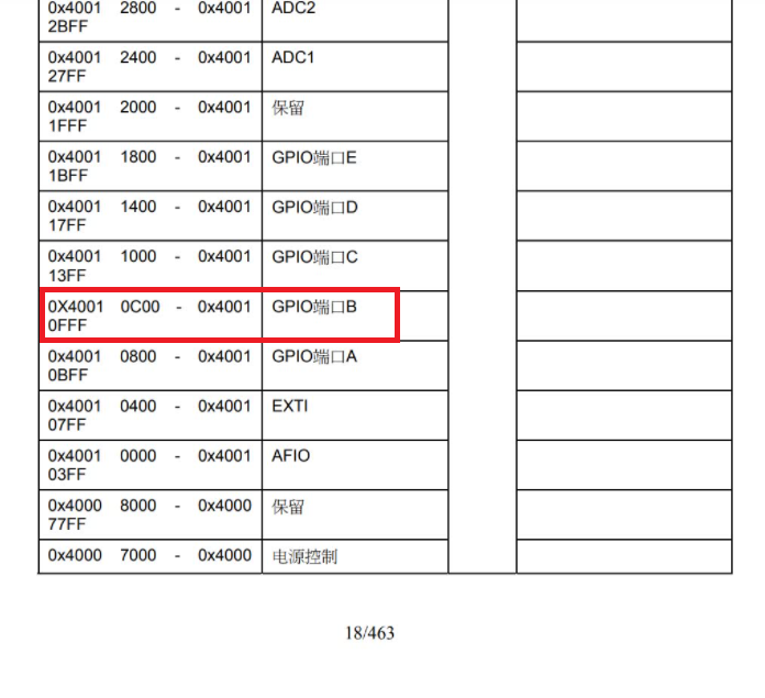
(2) Find the port configuration of GPIO register. The offset address of low register is 0X00
Thus, the address of gpiob - > CRL is 0X4001 0C00
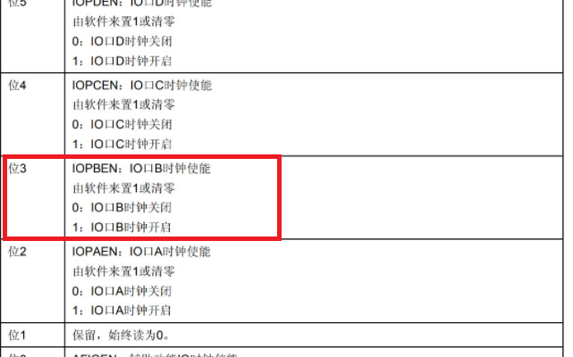
(3) Find that the address of the clock enable register is bit 3 of RCC_APB2ENR register, which controls the opening and closing of GPIOB clock, and set 1 to control the opening of clock
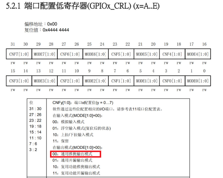
(4) Locate port configuration low register (GPIOx_CRL)
The CNF bit is used to configure the input / output mode. Here, the general push-pull output mode is selected according to the function, which is realized through the following code
GPIOC_CRH &= ~(0x0F<<(4*5));
GPIOC_CRH |= (1<<(4*5));
The MODE bit is used to configure the speed. Here, the maximum speed 2MHz is selected
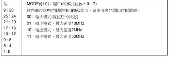
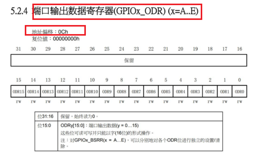
(5) Locate port output register (GPIOx_ODR)
The port output register is a pin level output register, which needs to be controlled to turn on and off the LED.
3. Initial preparation
(1) Establish project template
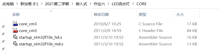
In order to better learn stm32, it is necessary to call library functions and establish project templates. Create a new general folder to store all programs of the project, and then create six folders: CORE, HARDWARE, OBJ, FWLIB, SYSTEM and USER.
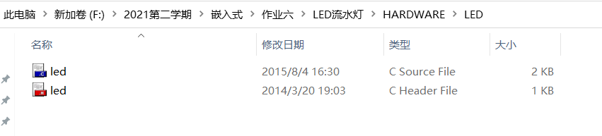
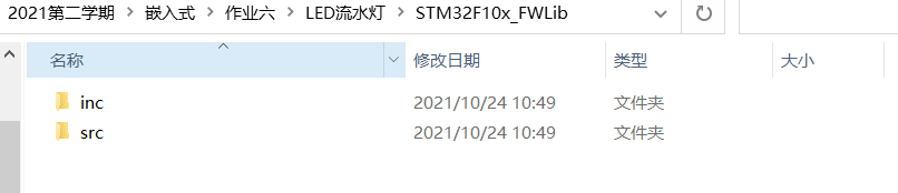
The HARDWARE folder is used to store peripheral HARDWARE code, OBJ is used to store generated debugging code, and FWLIB is various. c and. h files
The information is available here Punctual atom openedv data download address , I downloaded the rct6 data of the mini board, as follows
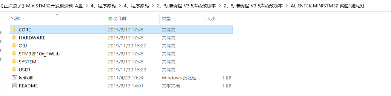 What I need to do now is to transfer the files in the data to the corresponding folder I have created
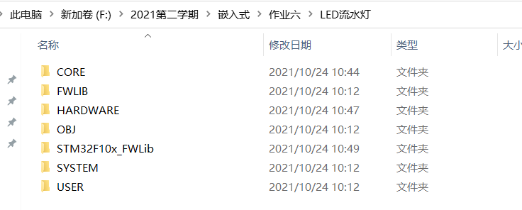
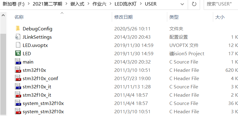
The contents of each folder are as follows
- CORE
- HARDWARE
- STM32F10x_FWLib
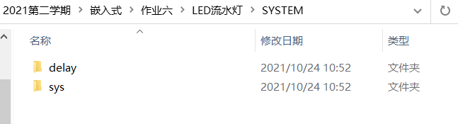
- SYSTEM
- USER
(2) Build project
Open keil software
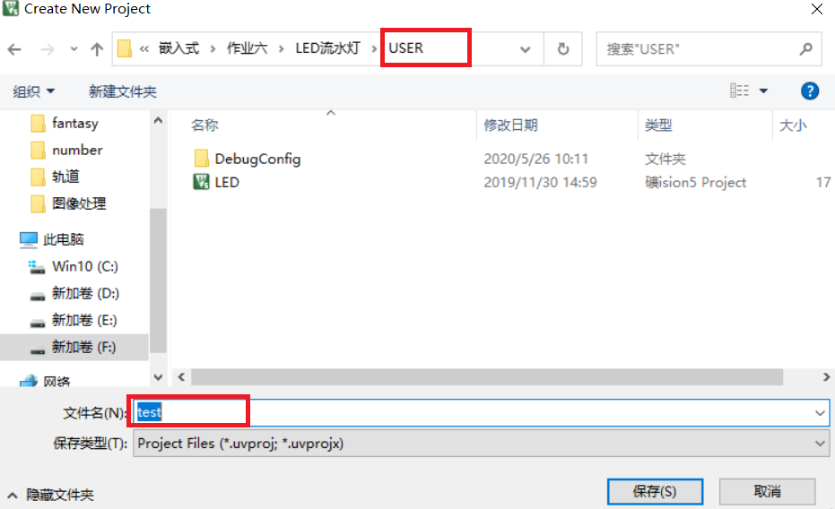
Click New uVision Project in Project in the keil menu bar to create a new Project and save it to the USER folder
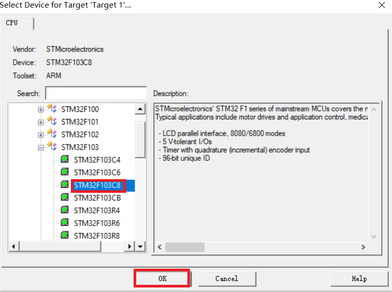
Select STM32F103C8 for the device and click OK
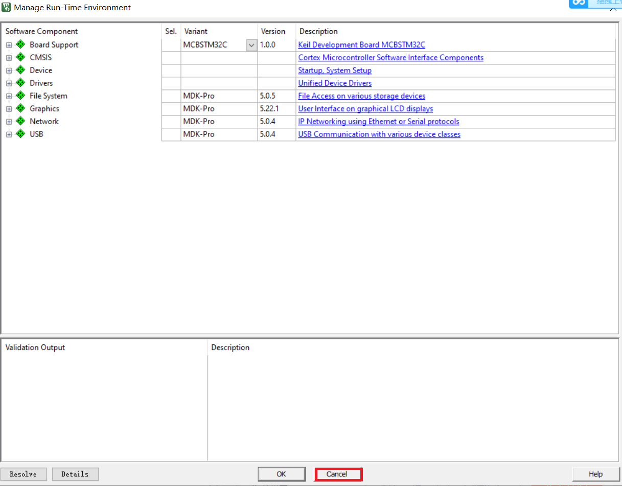
Note that in the pop-up manage runtime environment window, click cancel
Right click Target 1 and select Manage Project Items
In the upper right corner of the second column, create the name of the group
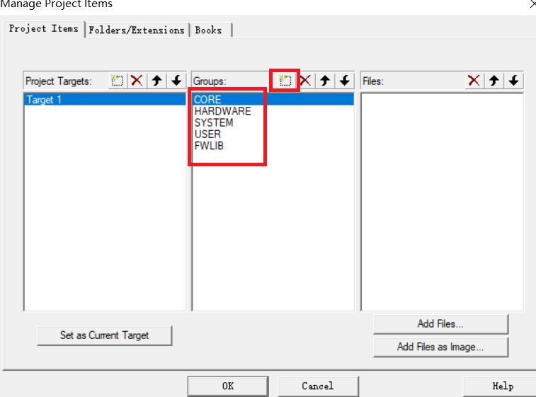
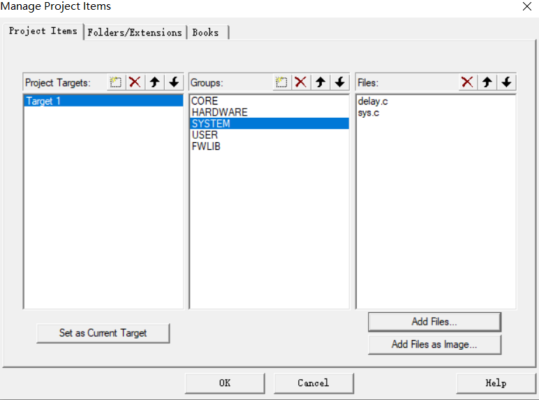
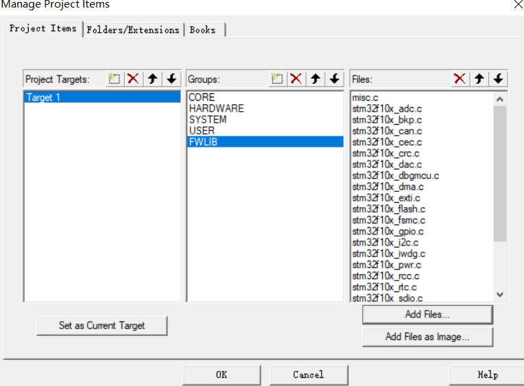
Add files in each group. The files are in several folders of the project created in the previous step, as follows
- CORE
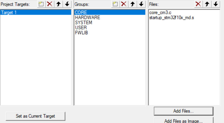
- HARDWARE
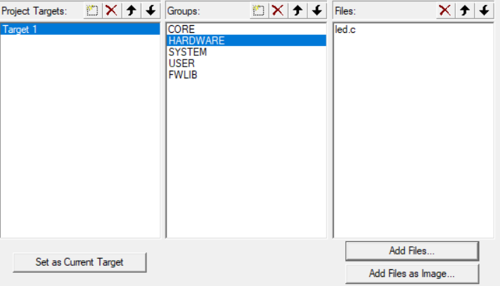
- SYSTEM
- USER
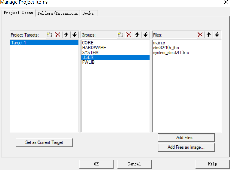
- FWLIB
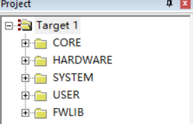
You can see the added groups
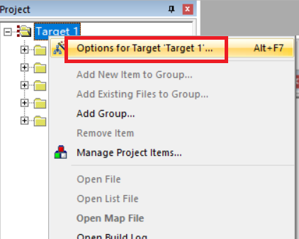
(3) Disposition
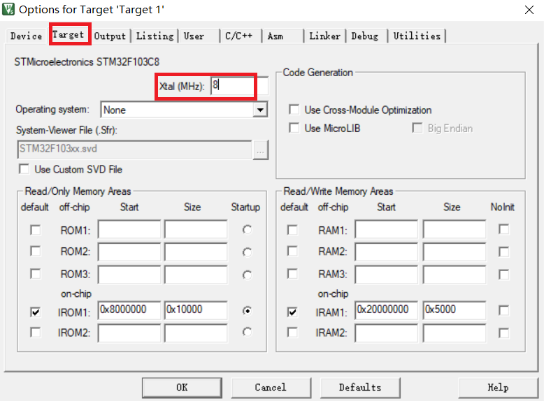
Right click Target1 and select Options for Target 'Target 1'
In the Target column, modify the crystal oscillator frequency value to 8
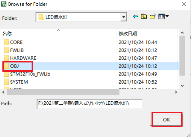
In the Output column, click Select Folder for Objects, select the directory where the generated hex file is stored, select it to be stored in the OBJ folder created earlier, and then check Create HEX File to generate hex files and download them to the development board
In the column of C/C + +, fill in the column of Define with USE_STDPERIPH_DRIVER,STM32F10X_MD, and then add paths in Include Paths, as shown in the figure
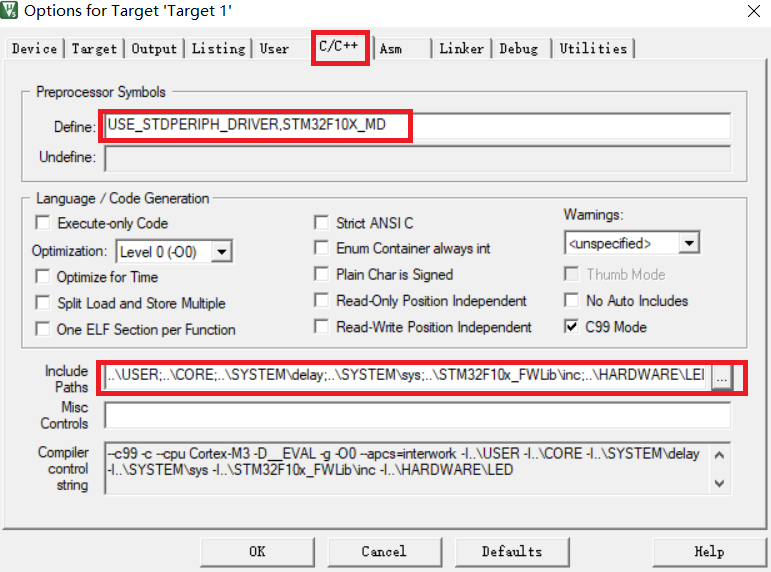 Add the first few folders to the entry path, and then click OK
 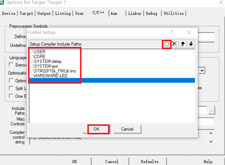 Here, the new project template is basically completed.
(4) Configure GPIO ports
Configure the GPIO port according to the three steps of GPIO port initialization and setting mentioned in the experimental principle
The first is the clock setting
RCC_APB2PeriphClockCmd(RCC_APB2Periph_GPIOB, ENABLE); //Turn on GPIOB port clock
Then the input / output setting and maximum rate setting. The output mode selected here is universal push-pull output, and the maximum rate is 2M
 GPIO_InitTypeDef   GPIO_InitStruct;

	GPIO_InitStruct.GPIO_Mode=GPIO_Mode_Out_PP;  			//The output mode is universal push-pull output
	GPIO_InitStruct.GPIO_Pin=GPIO_Pin_4 ;             		//The selected output port is GPIO_ Pin_ four
	GPIO_InitStruct.GPIO_Speed=GPIO_Speed_2MHz;				//The output speed is 2M

	GPIO_Init(GPIOA,&GPIO_InitStruct);
4. Code
(1)led.h
#ifndef _LED_H
#define _LED_H

#include "stm32f10x.h"
void LED_R_TOGGLE(void);
void LED_G_TOGGLE(void);
void LED_Y_TOGGLE(void);
void LED_Init(void);
#endif
(2)led.c
#include "led.h"
#include "delay.h"

void LED_Init(void)
{
	RCC_APB2PeriphClockCmd(RCC_APB2Periph_GPIOA|RCC_APB2Periph_GPIOB|RCC_APB2Periph_GPIOC,ENABLE);  //Turn on the clock of the peripheral GPIOB

	GPIO_InitTypeDef   GPIO_InitStruct;

	GPIO_InitStruct.GPIO_Mode=GPIO_Mode_Out_PP;  			//The output mode is universal push-pull output
	GPIO_InitStruct.GPIO_Pin=GPIO_Pin_4 ;             //The selected port is GPIO_ Pin_ four
	GPIO_InitStruct.GPIO_Speed=GPIO_Speed_2MHz;				//The output speed is 2M
	GPIO_Init(GPIOA,&GPIO_InitStruct);

	GPIO_InitStruct.GPIO_Mode=GPIO_Mode_Out_PP;  			//The output mode is universal push-pull output
	GPIO_InitStruct.GPIO_Pin=GPIO_Pin_10 ;             //The selected port is GPIO_ Pin_ one
	GPIO_InitStruct.GPIO_Speed=GPIO_Speed_2MHz;				//The output speed is 2M
	GPIO_Init(GPIOB,&GPIO_InitStruct);

	GPIO_InitStruct.GPIO_Mode=GPIO_Mode_Out_PP;  			//The output mode is universal push-pull output
	GPIO_InitStruct.GPIO_Pin=GPIO_Pin_14 ;             //The selected port is GPIO_ Pin_ fourteen
	GPIO_InitStruct.GPIO_Speed=GPIO_Speed_2MHz;				//The output speed is 2M
	GPIO_Init(GPIOC,&GPIO_InitStruct);
}

void LED_R_TOGGLE(void)
{
	GPIO_SetBits(GPIOA, GPIO_Pin_4);
	delay_ms(500);
	GPIO_ResetBits(GPIOA,GPIO_Pin_4);
}
void LED_G_TOGGLE(void)
{
	GPIO_SetBits(GPIOB, GPIO_Pin_10);
	delay_ms(500);
	GPIO_ResetBits(GPIOB,GPIO_Pin_10);
}
void LED_Y_TOGGLE(void)
{
	GPIO_SetBits(GPIOC, GPIO_Pin_14);
	delay_ms(500);
	GPIO_ResetBits(GPIOC,GPIO_Pin_14);
}
(3)delay.h
#ifndef __DELAY_H
#define __DELAY_H
#include "sys.h"

void delay_init(void);
void delay_ms(u16 nms);
void delay_us(u32 nus);

#endif
(4)delay.c
#include "delay.h"
//
//If you need to use OS, include the following header file
#if SYSTEM_SUPPORT_OS
#include "includes.h" 					// ucos usage
#endif

static u8  fac_us=0;							//Delay multiplier
static u16 fac_ms=0;							//MS delay multiplier, in ucos, represents the number of ms per beat


#if SYSTEM_SUPPORT_OS 							// If system_ SUPPORT_ The OS is defined, indicating that the OS is to be supported (not limited to UCOS)
#ifdef  	 OS_CRITICAL_METHOD 						// OS_CRITICAL_METHOD is defined to support UCOSII
#define delay_osrunning 		 OSRunning 			// Whether the OS is running flag, 0, not running; 1. In operation
#define delay_ostickspersec 	 OS_TICKS_PER_SEC 	// OS clock beat, i.e. scheduling times per second
#define delay_osintnesting  	 OSIntNesting 		// Break nesting level, that is, the number of times to break nesting
#endif

//Support UCOSIII
#ifdef  	 CPU_CFG_CRITICAL_METHOD 					// CPU_CFG_CRITICAL_METHOD is defined to support UCOSIII
#define delay_osrunning 		 OSRunning 			// Whether the OS is running flag, 0, not running; 1. In operation
#define delay_ostickspersec 	 OSCfg_TickRate_Hz 	// OS clock beat, i.e. scheduling times per second
#define delay_osintnesting  	 OSIntNestingCtr 		// Break nesting level, that is, the number of times to break nesting
#endif

//In case of us level delay, turn off task scheduling (to prevent interrupting us level delay)
void delay_osschedlock(void)
{
#ifdef CPU_CFG_CRITICAL_METHOD    				// Use UCOSIII
	OS_ERR err;
	OSSchedLock(&err);							//In ucosiiii mode, scheduling is prohibited to prevent interruption and delay
#else 											// Otherwise, UCOSII
	OSSchedLock();								//In UCOSII mode, scheduling is prohibited to prevent interruption and delay
#endif
}

//Resume task scheduling in case of us level delay
void delay_osschedunlock(void)
{
#ifdef CPU_CFG_CRITICAL_METHOD    				// Use UCOSIII
	OS_ERR err;
	OSSchedUnlock(&err);						//UCOSIII mode, resume scheduling
#else 											// Otherwise, UCOSII
	OSSchedUnlock();							//UCOSII mode, resume scheduling
#endif
}

//Call the delay function of the OS
//ticks: delayed beats
void delay_ostimedly(u32 ticks)
{
#ifdef CPU_CFG_CRITICAL_METHOD
	OS_ERR err;
	OSTimeDly(ticks,OS_OPT_TIME_PERIODIC,&err);	//Ucosiiii delay adopts periodic mode
#else
	OSTimeDly(ticks);							//UCOSII delay
#endif
}

//systick interrupt service function, which is used when using ucos
void SysTick_Handler(void)
{
	if(delay_osrunning==1)						//When the OS starts running, it performs normal scheduling processing
	{
		OSIntEnter();							//Entry interrupt
		OSTimeTick();       					//Call ucos clock service program
		OSIntExit();       	 					//Trigger task switching soft interrupt
	}
}
#endif

//Initialization delay function
//When using OS, this function initializes the clock beat of OS
//SYSTICK's clock is fixed to 1 / 8 of HCLK's clock
//SYSCLK: system clock
void delay_init()
{
#if SYSTEM_SUPPORT_OS   							// If necessary, support OS
	u32 reload;
#endif
	SysTick_CLKSourceConfig(SysTick_CLKSource_HCLK_Div8);	//Select external clock HCLK/8
	fac_us=SystemCoreClock/8000000;				//Is 1 / 8 of the system clock
#if SYSTEM_SUPPORT_OS   							// If necessary, support OS
	reload=SystemCoreClock/8000000;				//The number of counts per second is in M
	reload*=1000000/delay_ostickspersec;		//According to delay_ostickspersec sets the overflow time
												//reload is a 24 bit register with a maximum value of 16777216. At 72M, it is about 1.86s
	fac_ms=1000/delay_ostickspersec;			//Represents the minimum unit that the OS can delay

	SysTick->CTRL|=SysTick_CTRL_TICKINT_Msk;   	//Enable SYSTICK interrupt
	SysTick->LOAD=reload; 						//Every 1/delay_ostickspersec is interrupted once per second
	SysTick->CTRL|=SysTick_CTRL_ENABLE_Msk;   	//Turn on SYSTICK

#else
	fac_ms=(u16)fac_us*1000;					//Under non OS, it represents the number of systick clocks required for each ms
#endif
}

#if SYSTEM_SUPPORT_OS   							// If necessary, support OS
//Delay nus
//nus is the number of us to delay
void delay_us(u32 nus)
{
	u32 ticks;
	u32 told,tnow,tcnt=0;
	u32 reload=SysTick->LOAD;					//Value of LOAD
	ticks=nus*fac_us; 							//Number of beats required
	tcnt=0;
	delay_osschedlock();						//Prevent OS scheduling and interrupt us delay
	told=SysTick->VAL;        					//Counter value when entering
	while(1)
	{
		tnow=SysTick->VAL;
		if(tnow!=told)
		{
			if(tnow<told)tcnt+=told-tnow;		//Note that SYSTICK is a decrement counter
			else tcnt+=reload-tnow+told;
			told=tnow;
			if(tcnt>=ticks)break;				//If the time exceeds / equals the time to be delayed, exit
		}
	};
	delay_osschedunlock();						//Resume OS scheduling
}
//Delay nms
//nms: number of ms to delay
void delay_ms(u16 nms)
{
	if(delay_osrunning&&delay_osintnesting==0)	//If the OS is already running and is not in an interrupt (task scheduling cannot be performed in an interrupt)
	{
		if(nms>=fac_ms)							//The delay time is greater than the minimum time period of the OS
		{
   			delay_ostimedly(nms/fac_ms);		//OS delay
		}
		nms%=fac_ms;							//The OS can no longer provide such a small delay, so it adopts the ordinary delay mode
	}
	delay_us((u32)(nms*1000));					//Common mode delay
}
#else / / when OS is not used
//Delay nus
//nus is the number of us to delay
void delay_us(u32 nus)
{
	u32 temp;
	SysTick->LOAD=nus*fac_us; 					//Time loading
	SysTick->VAL=0x00;        					//Clear counter
	SysTick->CTRL|=SysTick_CTRL_ENABLE_Msk ;	//Start counting down
	do
	{
		temp=SysTick->CTRL;
	}while((temp&0x01)&&!(temp&(1<<16)));		//Waiting time arrives
	SysTick->CTRL&=~SysTick_CTRL_ENABLE_Msk;	//Turn off counter
	SysTick->VAL =0X00;      					 //Clear counter
}
//Delay nms
//Note the range of nms
//Systick - > load is a 24 bit register, so the maximum delay is:
//nms<=0xffffff*8*1000/SYSCLK
//SYSCLK is in Hz and NMS is in ms
//For 72M, NMS < = 1864
void delay_ms(u16 nms)
{
	u32 temp;
	SysTick->LOAD=(u32)nms*fac_ms;				//Time loading (systick - > load is 24bit)
	SysTick->VAL =0x00;							//Clear counter
	SysTick->CTRL|=SysTick_CTRL_ENABLE_Msk ;	//Start counting down
	do
	{
		temp=SysTick->CTRL;
	}while((temp&0x01)&&!(temp&(1<<16)));		//Waiting time arrives
	SysTick->CTRL&=~SysTick_CTRL_ENABLE_Msk;	//Turn off counter
	SysTick->VAL =0X00;       					//Clear counter
}
#endif
(5)main.c
#include  "stm32f10x.h"
#include "delay.h"
#include "led.h"
int main(void)
{
	LED_Init();
	delay_init();	                //Use the system tick timer and delay initialization

	while(1)						//Cycle on
	{
		LED_R_TOGGLE();
		delay_ms(500);				//Delay 1s after the red light is on
		LED_G_TOGGLE();
		delay_ms(500);				//Delay 1 s after the green light is on
		LED_Y_TOGGLE();
		delay_ms(500);				//Delay 1s after the yellow light is on
	}
}
5. Compile to generate HEX file
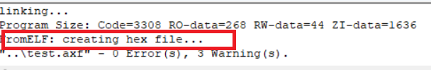
Compile successfully, generate HEX file
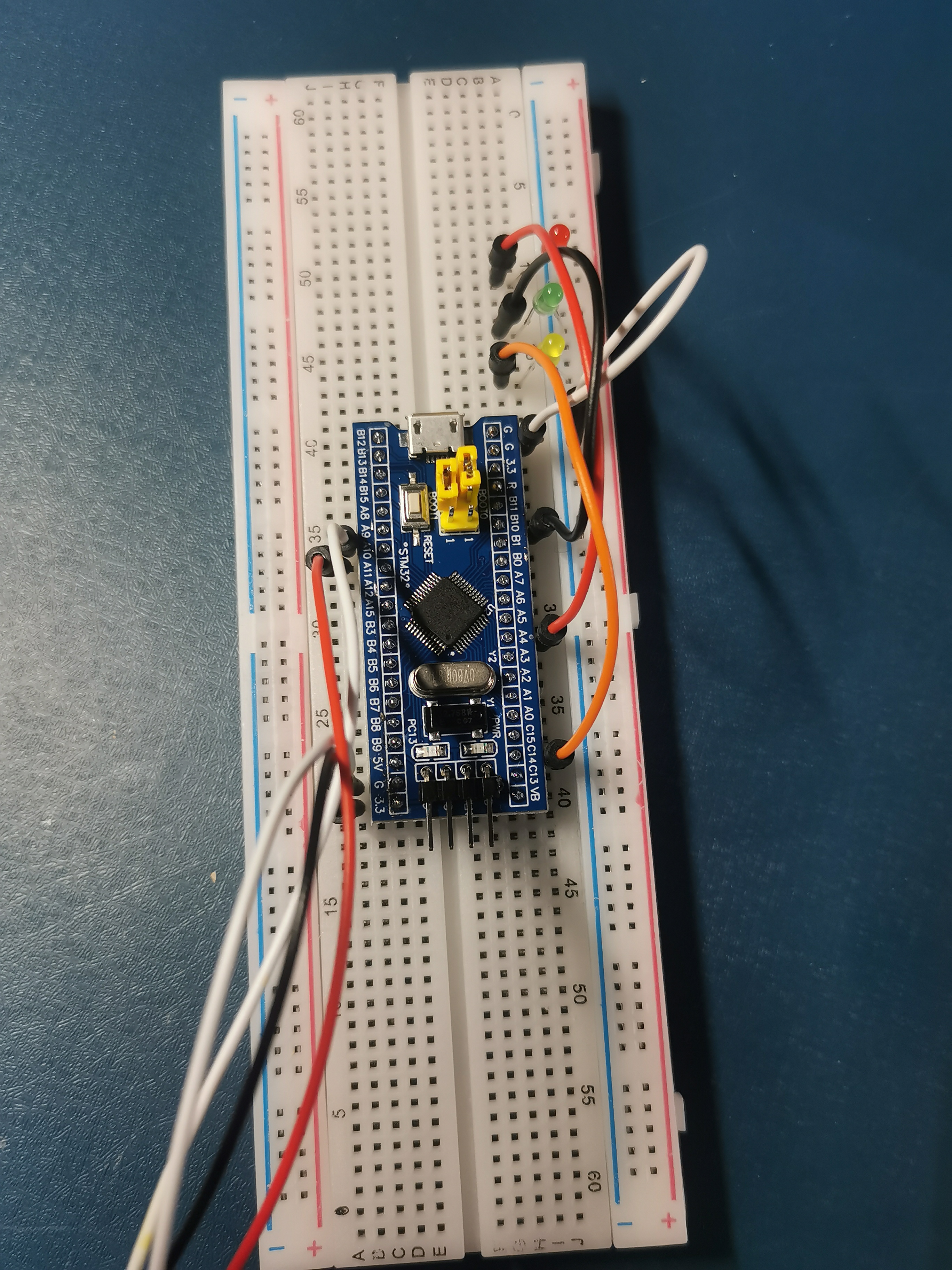
6. Hardware connection
(1) Use bread board to build circuit
According to the chip manual, build the circuit on the bread board. The connection method is as follows
(2) Install serial driver
Install the usb serial port driver on the computer, and a new serial port device (COM3) can be searched in the device manager
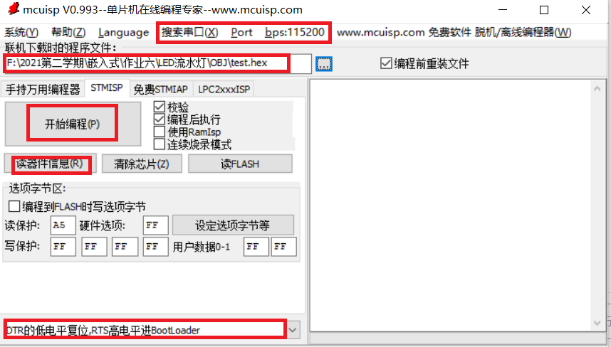
(3) Burn
Run the burning software mcuisp to configure
- Click search serial port to automatically search serial port, and select baud rate of 256000 in bps
- Lower left corner setting: DTR low level reset, RTS high level into BootLoader
- Read the device information. At this time, if the information in the interface appears, it indicates that the serial port and MCU are successfully connected.
- Select hex file
- Click start programming to download the program
The HEX file is successfully burned into the chip.
3, Experimental results
It can be seen that the effect of running water light, red light, green light and yellow light flash in turn
4, Experimental summary
This experiment was very challenging for me. At first, I didn't have a clue, but later, I solved many problems by constantly consulting materials and asking my classmates. In the process of hands-on practice, I also learned and understood the basic knowledge about stm32. While understanding the register principle, I also learned the three steps of GPIO port initialization and setting, which is very helpful for me to learn this course.
5, References
https://blog.csdn.net/big_blingbling/article/details/81427764
https://blog.csdn.net/weixin_42827999/article/details/101699674