The above topic was one of the topics that our laboratory came up with when we were new. It mainly investigated the knowledge of odd frequency division and even frequency division principles and timing logic such as counters. In combinatorial logic, it only included one out of two data selectors, which was not difficult. For us who had only studied for less than two months at that time, the difficulty of this topic was moderate. Let's analyze the implementation of the topic.
Even frequency division
Principle introduction:
Even frequency division is easy to understand. For example, if the frequency is 1 / 4 of the clk signal, its period is 4 times that of the clk signal. Therefore, when the value of the counter is equal to half of the frequency division coefficient or equal to the frequency division coefficient, the signal is reversed.
Taking the frequency division 4 in the following figure as an example, use the counter cnt to count, add 1 at the rising edge of the clock, flip div_4 once when counting to (4 / 2-1), flip it again when counting to (4-1), and repeat it periodically to get the frequency division 4 clock div_4 .
Even frequency division (4) source code:
module fenpin_4(
    input clk,
    input rst_n,
	output reg clk_div
    );
    parameter NUM_DIV = 4;
	reg[4:0] cnt;
always @(posedge clk)begin
    if(!rst_n)
        cnt <= 0;
	 else if(cnt == NUM_DIV - 1'b1)
		cnt <= 0;
    else
        cnt <= cnt + 1'b1;
end
always @(posedge clk)
    if(!rst_n)
        clk_div <= 1'b1;
    else if(cnt < NUM_DIV / 2)
        clk_div <= 1'b1;
    else
        clk_div <= 1'b0;


endmodule
tb file:
module tb_fenpin_4;

	// Inputs
	reg clk;
	reg rst_n;

	// Outputs
	wire clk_div;

	// Instantiate the Unit Under Test (UUT)
	fenpin_4 uut (
		.clk(clk),
		.rst_n(rst_n),
		.clk_div(clk_div)
	);
always #10 clk = ~clk;
	initial begin
		// Initialize Inputs
		clk = 0;
		rst_n = 0;

		// Wait 100 ns for global reset to finish
		#100;
        rst_n = 1;
		// Add stimulus here

	end

endmodule
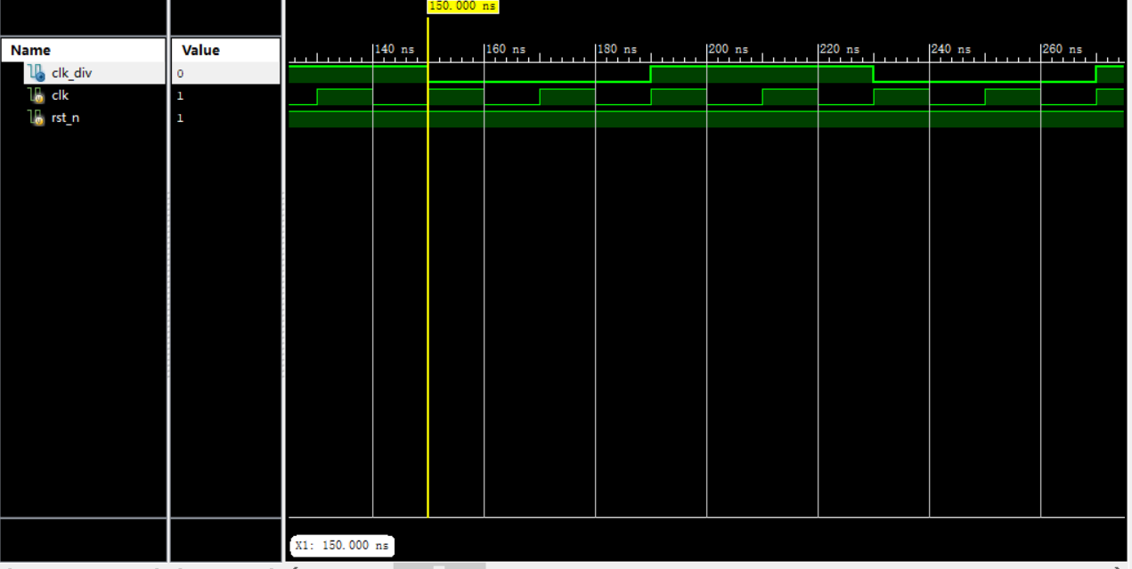
Simulation waveform:
Odd frequency division
Principle introduction:
Odd frequency division is similar to even frequency division. The principle is slightly more complex. It is not possible to take the frequency division coefficient directly like even frequency division. Generally, the signal is reversed to directly realize the duty cycle of 50%. At this time, we need to get it through the combined logic operation of two frequency division signals. Let's analyze the design idea.
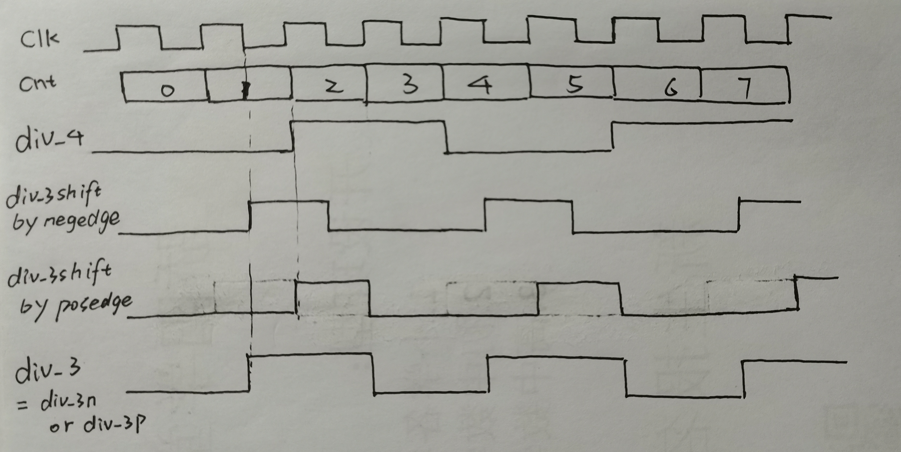
As shown in the figure below, taking the frequency division of 3 as an example, use the counter cnt to count and add 1 at the rising edge of the clock. When cnt counts to (3 / 2 = 1) and the clock is at the falling edge, clk_out_1 (div_3shift by edge in the figure) Perform a flip. When the cnt counts the frequency division coefficient 3 and the clock is at the falling edge, flip clk_out_1 again. Finally, the signal clk_out_1 with a duty cycle of 1 / 3 is obtained.
At the same time, when the cnt counts to (3 / 2 = 1) and the clock is at the upper and lower edges, clk_out_1 (div_3shift by position in the figure) is flipped once. When the cnt counts to the frequency division coefficient 3 and the clock is at the upper and lower edges, clk_out_1 is flipped again. Finally, the signal clk_out_1 with a duty cycle of 1 / 3 is obtained.
Then the two signals are passed through the "or" gate to obtain div_3 signal.
(3) frequency division source code:
module fenpin_3(
    input clk,
    input rst_n,
    output clk_div
    );

    parameter NUM_DIV = 3;
    reg[2:0] cnt1;
    reg[2:0] cnt2;
    reg    clk_div1, clk_div2;

always @(posedge clk or negedge rst_n)
    if(!rst_n)
        cnt1 <= 0;
    else if(cnt1 < NUM_DIV - 1)
        cnt1 <= cnt1 + 1'b1;
    else
        cnt1 <= 0;

always @(posedge clk or negedge rst_n)
    if(!rst_n)
        clk_div1 <= 1'b1;
    else if(cnt1 < NUM_DIV / 2)
        clk_div1 <= 1'b1;
    else
        clk_div1 <= 1'b0;

always @(negedge clk or negedge rst_n)
    if(!rst_n)
       cnt2 <= 0;
    else if(cnt2 < NUM_DIV - 1)
       cnt2 <= cnt2 + 1'b1;
    else
       cnt2 <= 0;

always @(negedge clk or negedge rst_n)
    if(!rst_n)
        clk_div2 <= 1'b1;
    else if(cnt2 < NUM_DIV / 2)
        clk_div2 <= 1'b1;
    else
        clk_div2 <= 1'b0;

    assign clk_div = clk_div1 | clk_div2;

endmodule
tb file:
module tb_fenpin_3;

	// Inputs
	reg clk;
	reg rst_n;

	// Outputs
	wire clk_div;

	// Instantiate the Unit Under Test (UUT)
	fenpin_3 uut (
		.clk(clk),
		.rst_n(rst_n),
		.clk_div(clk_div)
	);
always #10 clk = ~clk;
	initial begin
		// Initialize Inputs
		clk = 0;
		rst_n = 0;

		// Wait 100 ns for global reset to finish
		#100;
		rst_n = 1;

		// Add stimulus here

	end

endmodule
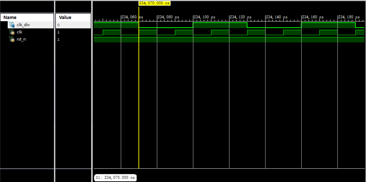
Simulation waveform:
The above is an introduction to the main framework of this topic. Odd frequency division and even frequency division are very commonly used in our projects, such as dynamic nixie tube and other projects requiring time.
To get down to business, with the above foundation, it's easy to do the original topic. Next, I'll post the code of the interview topic here.
Source code of the topic:
module pro_2(
    input clk,
	 input sel,
    input rst_n,
	 output reg out
    );
    parameter NUM_DIV = 15;
    parameter NUM_DIV_1 = 18;
	 reg[4:0] cnt1;
    reg[4:0] cnt2;
	 reg[4:0] cnt3;
    reg    clk_div1, clk_div2,clk_div3;
    wire clk_div;
always @(posedge clk  or negedge rst_n)
    if(!rst_n)
        cnt1 <= 0;
    else if(cnt1 < NUM_DIV - 1)
        cnt1 <= cnt1 + 1'b1;
    else
        cnt1 <= 0;
always @(posedge clk  or negedge rst_n)
    if(!rst_n)
        clk_div1 <= 1'b1;
    else if(cnt1 < NUM_DIV / 2)
        clk_div1 <= 1'b1;
    else
        clk_div1 <= 1'b0;
always @(negedge clk or negedge rst_n)
    if(!rst_n)
       cnt2 <= 0;
    else if(cnt2 < NUM_DIV - 1)
       cnt2 <= cnt2 + 1'b1;
    else
       cnt2 <= 0;
always @(negedge clk or negedge rst_n)
    if(!rst_n)
        clk_div2 <= 1'b1;
    else if(cnt2 < NUM_DIV / 2)
        clk_div2 <= 1'b1;
    else
        clk_div2 <= 1'b0;

assign clk_div = clk_div1 | clk_div2;//15 frequency division


always @(posedge clk)begin
    if(!rst_n)
        cnt3 <= 0;
	 else if(cnt3 == NUM_DIV_1 - 1'b1)
			cnt3 <= 0;
    else
        cnt3 <= cnt3 + 1'b1;
end
always @(posedge clk)
    if(!rst_n)
        clk_div3 <= 1'b1;
    else if(cnt3 < NUM_DIV_1 / 2)
        clk_div3 <= 1'b1;
    else
        clk_div3 <= 1'b0;//18 frequency division

always@(*)begin
    if(sel==0)
	   out = clk_div;
	 else if(sel==1)
	   out = clk_div3;
end


endmodule
tb file :
module tb_pro2;

	// Inputs
	reg clk;
	reg sel;
	reg rst_n;

	// Outputs
	wire out;

	// Instantiate the Unit Under Test (UUT)
	pro_2 uut (
		.clk(clk),
		.sel(sel),
		.rst_n(rst_n),
		.out(out)
	);
always #10 clk = ~clk;
	initial begin
		// Initialize Inputs
		clk = 0;
		sel = 0;
		rst_n = 0;

		// Wait 100 ns for global reset to finish
		#100;
		sel = 0;
		rst_n = 1;

		#100000;
		sel = 1;
   		// Add stimulus here

	end

endmodule
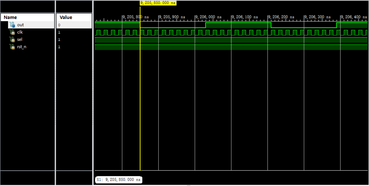
Simulation waveform:
When sel control signal is 0, 15 frequency division is output
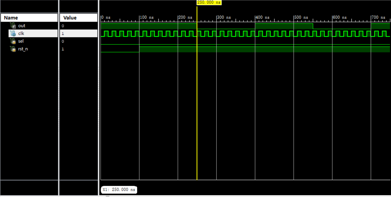
When sel control signal is 1, 18 frequency division is output