High Availability HA (High Availability) is one of the factors that must be considered in the architecture design of distributed systems. It usually refers to reducing the time when the system cannot provide services through design.
Assuming that the system can always provide services, we say that the availability of the system is 100%. If the system runs every 100 time units, one time unit cannot provide service. We say that the availability of the system is 99%. The high availability target of many companies is 4 9s, or 99.99%, which means that the annual downtime of the system is 8.76 hours.
So how to ensure the high availability of the system
Firstly, single point problems are not allowed in each node of the whole architecture, because single point must be the greatest risk point of high availability. We should avoid single point problems in the system design process.
In terms of implementation methods, cluster deployment or redundant deployment are generally adopted. This design allows other nodes to continue to use if one node fails.
Necessity of high availability design in Redis
As a high-performance Nosq middleware, Redis will store a lot of hot data in Redis. Once the Redis server fails, all related business access problems will occur. In addition, even if the scheme of database disclosure is designed, a large number of requests for access to the database can easily lead to database bottlenecks and greater disasters.
In addition, Redis cluster deployment can also bring additional benefits:
- The load (performance) of Redis's QPS is already very high, but if the concurrency is very high, the performance will still be affected. At this time, we hope to have more Redis services to complete the work
- Capacity expansion (horizontal expansion). The second is for storage. Because all Redis data is stored in memory, if the amount of data is large, it is easy to be limited by hardware. The efficiency and cost ratio of upgrading hardware is too low, so we need a horizontal expansion method
Redis provides high availability solutions, including the following:
- Master slave replication (used to realize read-write separation)
- Sentinel mechanism (master election)
- Cluster mechanism (realizing data fragmentation)
Redis master slave method
The master-slave replication mode is simply to copy the data of one Redis server to other Redis servers. The source responsible for copying data is called the master, and the node that passively receives and synchronizes data is called the slave. Data replication is one-way, as shown in Figure 5-1. There are many variants of the master-slave mode.
This idea is used in many components, such as the master-slave replication of mysql, the master-slave replication of redis, the master-slave replication of activemq, the data replication mechanism in kafka, etc. Therefore, we need to draw inferences from one instance and master them thoroughly.
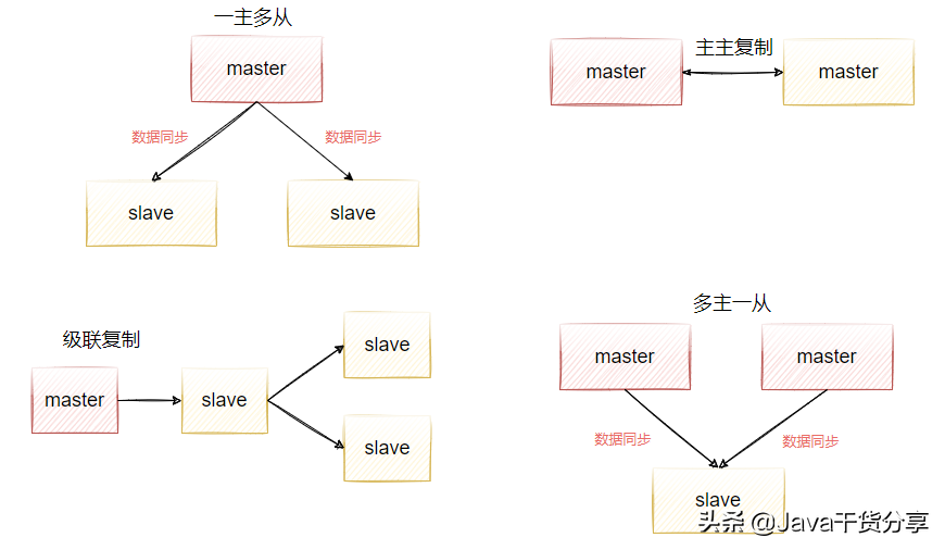
Figure 5-1
Benefits of master-slave replication
- Data redundancy. Master-slave replication realizes the hot standby of data. It is another way of data redundancy in addition to the persistence mechanism.
- Read write separation enables the database to support greater concurrency. It is particularly important in the report. Because some report sql statements are very slow, the table is locked and the foreground service is affected. If the foreground uses master and the report uses slave, the report sql will not cause the foreground lock and ensure the foreground speed.
- Load balancing, based on master-slave replication and combined with the read-write separation mechanism, the master node can provide write services and the slave node can provide services. In the scenario of more reads and less writes, the slave node can be increased to share the load of redis server read operations, so as to greatly improve the concurrency of redis server
- Ensure high availability. As a backup database, if the master node fails, you can switch to the slave node to continue working to ensure high availability of redis server.
How Redis configures master-slave replication
It should be noted that the master-slave replication of Redis is initiated directly at the slave node. The master node does not need to do anything
There are three ways to enable master-slave replication in Redis.
- Add the following configuration replicaof < masterip > < masterport > to the redis.conf configuration file of the slave server
- It is configured by starting the command, that is, when starting the slave node, execute the following command
./redis-server ../redis.conf --replicaof <masterip> <masterport>
- After you start redis server, directly execute the following command in the client window redis > replicaof < masterip > < masterport >
Prepare three virtual machines
Prepare three virtual machines, and the three virtual machines need to be able to ping each other and access port 6379. If they can't access, close the firewall.
firewall-cmd --zone=public --add-port=6379/tcp --permanent
- 192.168.221.128(master)
- 192.168.221.129(slave)
- 192.168.221.130(slave)
Redis server needs to be installed on all three machines. The installation steps are as follows.
Note: Redis6 installation requires gcc version greater than 5.3, otherwise the installation will report an error.
# Upgrade to gcc 9.3:
yum -y install centos-release-scl
yum -y install devtoolset-9-gcc devtoolset-9-gcc-c++ devtoolset-9-binutils
scl enable devtoolset-9 bash
# It should be noted that the scl command is enabled only temporarily. Exiting the shell or restarting will restore the gcc version of the original system.
# If you want to use gcc 9.3 for a long time:
echo -e "\nsource /opt/rh/devtoolset-9/enable" >>/etc/profile
Start installation
cd /usr/local/
wget http://download.redis.io/releases/redis-6.0.9.tar.gz
tar -zxvf redis-6.0.9.tar.gz
cd redis-6.0.9
make
make test
make install PREFIX=/data/program/redis
cp redis.conf /data/program/redis/redis.conf
Demonstrate the configuration process
Add configurations on 192.168.221.129 and 192.168.221.130 according to the following operations respectively.
- Edit the redis.conf file, jump to the last line through shift+g, and add the following configuration: replica of 192.168.221.128 6379
- Start the two machines respectively. After successful startup, use the following command to view the cluster status redis > info replication
- You can see from the startup log that information has been copied from the master node during startup.
  66267:S 12 Jul 2021 22:21:46.013 * Loading RDB produced by version 6.0.9
  66267:S 12 Jul 2021 22:21:46.013 * RDB age 50 seconds
  66267:S 12 Jul 2021 22:21:46.013 * RDB memory usage when created 0.77 Mb
  66267:S 12 Jul 2021 22:21:46.013 * DB loaded from disk: 0.000 seconds
  66267:S 12 Jul 2021 22:21:46.013 * Ready to accept connections
  66267:S 12 Jul 2021 22:21:46.013 * Connecting to MASTER 192.168.221.128:6379
  66267:S 12 Jul 2021 22:21:46.014 * MASTER <-> REPLICA sync started
  66267:S 12 Jul 2021 22:21:46.015 * Non blocking connect for SYNC fired the event.
  66267:S 12 Jul 2021 22:21:46.016 * Master replied to PING, replication can continue...
  66267:S 12 Jul 2021 22:21:46.017 * Partial resynchronization not possible (no cached master)
  66267:S 12 Jul 2021 22:21:46.039 * Full resync from master: acb74093b4c9d6fb527d3c713a44820ff0564508:0
  66267:S 12 Jul 2021 22:21:46.058 * MASTER <-> REPLICA sync: receiving 188 bytes from master to disk
  66267:S 12 Jul 2021 22:21:46.058 * MASTER <-> REPLICA sync: Flushing old data
  66267:S 12 Jul 2021 22:21:46.058 * MASTER <-> REPLICA sync: Loading DB in memory
  66267:S 12 Jul 2021 22:21:46.060 * Loading RDB produced by version 6.2.4
  66267:S 12 Jul 2021 22:21:46.060 * RDB age 0 seconds
  66267:S 12 Jul 2021 22:21:46.060 * RDB memory usage when created 1.83 Mb
  66267:S 12 Jul 2021 22:21:46.060 * MASTER <-> REPLICA sync: Finished with success
If the log is not started, you can start it by the following method
Find the Redis configuration file redis.conf, open the configuration file, vi redis.conf; Find the logfile "" (below loglevel) through the query command of linux; Enter the log path in the colon, such as logfile“
/usr/local/redis/log/redis.log ", directories and files need to be created in advance. Redis will not create this file by default.
Then, by setting some key s on the master node, we will find that the data is synchronized to the two slave nodes immediately, thus completing the master-slave synchronization function. However, by default, the slave server is read-only. If you modify it directly on the slave server, an error will be reported. However, you can find an attribute in redis.conf of the slave server that allows the slave server to write, but this is not recommended. Because the changes on the slave server cannot be synchronized to the master, the data will not be synchronized
slave-read-only no
Principle analysis of Redis master-slave replication
Redis has two types of master-slave replication: full replication and incremental replication.
Full replication
As shown in Figure 5-2, it shows the overall sequence diagram of Redis master-Slave full replication. Full replication generally occurs in the Slave node initialization stage. At this time, all data on the master needs to be copied. The specific steps are as follows:
- Connect the slave server to the master server and send the SYNC command;
- After receiving the SYNC naming, the master server starts to execute the BGSAVE command to generate an RDB file and uses the buffer to record all write commands executed thereafter;
- After the master server BGSAVE executes, it sends snapshot files to all slave servers, and continues to record the executed write commands during sending (indicating data changes during RDB asynchronous snapshot generation);
- After receiving the snapshot file from the server, discard all old data and load the received snapshot;
- After sending the snapshot from the master server, start sending the write command in the buffer to the slave server;
- Loading the snapshot from the server, receiving the command request, and executing the write command from the main server buffer;
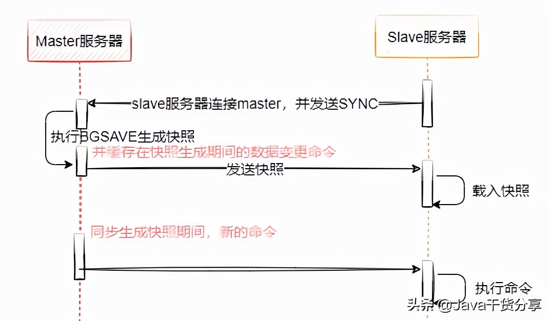
Figure 5-2
Question: how to handle the commands received by the master during RDB generation?
When generating RDB files, the master caches all new write commands in memory. After the slave node saves the RDB, copy the new write command to the slave node. (the same idea as during AOF rewriting)
After completing the above steps, all the operations of slave server data initialization are completed. At this time, the savle server can receive read requests from users. At the same time, the master-slave node enters the command propagation stage. In this stage, the master node sends its own write commands to the slave node, and the slave node receives and executes the commands, so as to ensure the data consistency of the master-slave node.
In the command propagation phase, in addition to sending write commands, the master and slave nodes also maintain the heartbeat mechanism: PING and REPLCONF ACK. The specific implementation is shown below.
- Execute on the slave server redis cli REPLCONF listening-port 6379 (send the replconf command to the primary database to specify its own port number)
- Start synchronization. Send the sync command to the master server to start synchronization. At this time, the master will send the snapshot file and cache commands.
  127.0.0.1:6379> sync
  Entering replica output mode...  (press Ctrl-C to quit)
  SYNC with master, discarding 202 bytes of bulk transfer...
  SYNC done. Logging commands from master.
  "ping"
  "ping"
- Slave will write the received contents to the temporary file on the hard disk. When writing is completed, the temporary file will replace the original RDB snapshot file. It should be noted that during the synchronization process, the slave will not block and can still process the client's commands. By default, the slave will respond to the command with the data before synchronization. If we want to read the data without dirty data, we can configure the following parameters in the redis.conf file to make the slave reply to the error: sync with master in progressslave serve stale data No
- After the replication phase ends, any non query statements executed by the master will be sent to the slave asynchronously. You can execute the set command on the master node, and you can see the following synchronization instructions on the slave node. redis > sync "set","11","11" "ping"
In addition, it should be noted that:
The master/slave replication strategy adopts optimistic replication, that is, it can be tolerated that the contents of the master/slave data are different within a certain period of time, but the two data will eventually be synchronized successfully.
Specifically, the master-slave synchronization process of redis is asynchronous, which means that the master will immediately return the results to the client after executing the commands requested by the client, and then synchronize the commands to the slave in an asynchronous manner. This feature ensures that the performance of the master will not be affected after the master/slave is enabled.
On the other hand, if the master/slave is disconnected due to network problems during the window with inconsistent data, and at this time, the master cannot know how many slave databases a command finally synchronizes to. However, redis provides a configuration item to restrict the master to be writable only when the data is synchronized to at least how many slaves:
min-replicas-to-write 3     Indicates that only when there are 3 or more slave connection to master,master Is writable

min-replicas-max-lag 10     Indicates permission slave The longest time to lose connection, if it hasn't been received in 10 seconds slave In response to the request, then master Think slave To disconnect
Modify the redis.conf of the master redis service, open these two configurations, and restart to see the effect
Incremental replication
Starting from Redis2.8, the master-slave node supports incremental replication and supports breakpoint retransmission. That is, if replication is abnormal or the network connection is disconnected, the replication can still continue to synchronize according to the last replication after system recovery, rather than full replication.
Its specific principle is: the master node and the slave node maintain a copy offset respectively, which represents the number of bytes passed from the master node to the slave node; When the master node propagates n bytes of data to the slave node each time, the offset of the master node increases by N; Every time the slave node receives n bytes of data from the master node, the offset of the slave node increases by n. The offset of the master and slave nodes can be saved in the master node_ repl_ Offset: 78130 and slave_ repl_ The offset fields can be viewed through the following command.
127.0.0.1:6379> info replication
# Replication
role:slave
master_host:192.168.221.128
master_port:6379
master_link_status:up
master_last_io_seconds_ago:1
master_sync_in_progress:0
slave_repl_offset:77864
slave_priority:100
slave_read_only:1
connected_slaves:0
master_replid:acb74093b4c9d6fb527d3c713a44820ff0564508
master_replid2:0000000000000000000000000000000000000000
master_repl_offset:77864
second_repl_offset:-1
repl_backlog_active:1   # Open copy buffer
repl_backlog_size:1048576  # Maximum buffer length
repl_backlog_first_byte_offset:771  # Starting offset to calculate the available range of the current cache
repl_backlog_histlen:77094  # To save the effective length of the data
No disk replication
As we said earlier, the working principle of Redis replication is based on the persistence implementation of RDB, that is, the master saves RDB snapshots in the background, and the slave receives and loads RDB files, but this method will have some problems.
- When the master disables RDB, if replication initialization is performed, Redis will still generate RDB snapshot. When the master starts next time, the RDB file will be recovered. However, because the time point of replication is uncertain, the recovered data may be at any time point. Will cause data problems
- When the performance of the hard disk is relatively slow (network hard disk), the initialization replication process will have an impact on the performance
Therefore, in versions after 2.8.18, Redis has introduced the option of hard disk free replication, which can directly send data without synchronizing through RDB files. This function can be enabled through the following configuration:
repl-diskless-sync yes
The master directly creates an rdb in memory and sends it to the slave. It will not land the disk locally
Notes for master-slave replication
The master-slave mode solves the problems of data backup and performance (separation of reading and writing), but there are still some shortcomings:
1. The first replication must be full replication. Therefore, if the primary node has a large amount of data, the replication delay is relatively long. At this time, try to avoid the peak of traffic and avoid blocking; If multiple slave nodes need to establish replication to the master node, consider staggering several slave nodes to avoid excessive bandwidth occupation of the master node. In addition, if there are too many slave nodes, you can also adjust the topology of master-slave replication from one master-slave structure to a tree structure.
2. In the case of one master-slave or one master-slave, if the master server hangs, the external services will not be available, and the single point problem has not been solved. If you manually switch the previous slave server to the master server every time, it will be time-consuming and laborious, and the service will not be available for a certain time.
Sentinel sentinel mechanism of Master automatic election
In the master/slave mode mentioned earlier, in a typical one master multi-slave system, slave plays the role of redundant data backup and separation of read and write in the whole system. When the master encounters an abnormal terminal, the developer can manually select a slave database to upgrade to the master, so that the system can continue to provide services. Then this process needs manual intervention, which is more troublesome; redis does not provide the function of automatic master election, but needs to be monitored with the help of a sentry.
What is a sentry
As the name suggests, the role of Sentry is to monitor the operation of Redis system. Its functions include two
- Monitor whether the master and slave are running normally
- When the master fails, the slave database is automatically upgraded to master
Sentinel is an independent process. The architecture after using sentinel is shown in Figure 5-3. At the same time, in order to ensure the high availability of sentinel, we will make cluster deployment for sentinel. Therefore, sentinel will not only monitor all master and slave nodes of Redis, but also monitor each other.
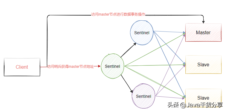
Figure 5-3
Configure sentinel cluster
Based on the previous master-slave replication, three sentinel nodes are added to realize the function of master election in redis.
- 192.168.221.128(sentinel)
- 192.168.221.129(sentinel)
- 192.168.221.130(sentinel)
sentinel Sentry is configured as follows:
- Copy the sentinel.conf file from the redis-6.0.9 source package to the redis/bin installation directory
cp /data/program/redis-6.0.9/sentinel.conf /data/program/redis/sentinel.conf
- Modify the following configuration
  # Where name refers to the name of the master to be monitored. The name is self-defined. ip and port refer to the ip and port number of the master. The last 2 represents the minimum number of votes, that is, at least several sentinel nodes need to think that the master is offline before it is really offline
  sentinel monitor mymaster 192.168.221.128 6379 2
  sentinel down-after-milliseconds mymaster 5000   # Indicates that if mymaster does not respond within 5s, it is considered SDOWN
  sentinel failover-timeout mymaster 15000         # It means that if mysaster still doesn't live after 15 seconds, start failover and upgrade one of the remaining slave to master
  logfile "/data/program/redis/logs/sentinels.log"  # Files need to be created in advance
- Start sentinel with the following command
./redis-sentinel ../sentinel.conf
- After successful startup, get the following information, indicating that the sentinel is started successfully and starts monitoring the cluster nodes
  103323:X 13 Jul 2021 15:16:28.624 # Sentinel ID is 2e9b0ac7ffbfca08e80debff744a4541a31b3951
  103323:X 13 Jul 2021 15:16:28.624 # +monitor master mymaster 192.168.221.128 6379 quorum 2
  103323:X 13 Jul 2021 15:16:28.627 * +slave slave 192.168.221.129:6379 192.168.221.129 6379 @ mymaster 192.168.221.128 6379
  103323:X 13 Jul 2021 15:16:28.628 * +slave slave 192.168.221.130:6379 192.168.221.130 6379 @ mymaster 192.168.221.128 6379
  103323:X 13 Jul 2021 15:16:48.765 * +fix-slave-config slave 192.168.221.130:6379 192.168.221.130 6379 @ mymaster 192.168.221.128 6379
  103323:X 13 Jul 2021 15:16:48.765 * +fix-slave-config slave 192.168.221.129:6379 192.168.221.129 6379 @ mymaster 192.168.221.128 6379
The configuration of the other two nodes is exactly the same as the above. Just monitor the master node. Mainly, the ip of the master node in the sentinel.conf file must not be 127.0.0.1, otherwise other sentinel nodes cannot communicate with it
When other sentinel sentinel nodes are started, the first started sentinel node will also output the following log, indicating that other sentinel nodes have joined.
+sentinel sentinel d760d62e190354654490e75e0b427d8ae095ac5a 192.168.221.129 26379 @ mymaster 192.168.221.128 6379
103323:X 13 Jul 2021 15:24:31.421
+sentinel sentinel dc6d874fe71e4f8f25e15946940f2b8eb087b2e8 192.168.221.130 26379 @ mymaster 192.168.221.128 6379
Simulate master node failure
We directly copy the master node of the redis master-slave cluster and stop it with the. / redis cli shutdown command. Then we observe the logs of the three sentinel sentinels. First, we look at the sentinel logs of the first sentinel, and get the following results.
103625:X 13 Jul 2021 15:35:01.241 # +new-epoch 9
103625:X 13 Jul 2021 15:35:01.244 # +vote-for-leader d760d62e190354654490e75e0b427d8ae095ac5a 9
103625:X 13 Jul 2021 15:35:01.267 # +odown master mymaster 192.168.221.128 6379 #quorum 2/2
103625:X 13 Jul 2021 15:35:01.267 # Next failover delay: I will not start a failover before Tue Jul 13 15:35:31 2021
103625:X 13 Jul 2021 15:35:02.113 # +config-update-from sentinel d760d62e190354654490e75e0b427d8ae095ac5a 192.168.221.129 26379 @ mymaster 192.168.221.128 6379
103625:X 13 Jul 2021 15:35:02.113 # +switch-master mymaster 192.168.221.128 6379 192.168.221.130 6379
103625:X 13 Jul 2021 15:35:02.113 * +slave slave 192.168.221.129:6379 192.168.221.129 6379 @ mymaster 192.168.221.130 6379
103625:X 13 Jul 2021 15:35:02.113 * +slave slave 192.168.221.128:6379 192.168.221.128 6379 @ mymaster 192.168.221.130 6379
103625:X 13 Jul 2021 15:35:07.153 # +sdown slave 192.168.221.128:6379 192.168.221.128 6379 @ mymaster 192.168.221.130 6379
+sdown indicates that the sentinel subjectively thinks that the master has stopped serving.
+odown indicates that the sentinel objectively thinks that the master is out of service (about subjective and objective, we will explain later).
Then the sentinel starts fault recovery, selects a slave to upgrade to master, and logs of other sentinel nodes.
76274:X 13 Jul 2021 15:35:01.240 # +try-failover master mymaster 192.168.221.128 6379
76274:X 13 Jul 2021 15:35:01.242 # +vote-for-leader d760d62e190354654490e75e0b427d8ae095ac5a 9
76274:X 13 Jul 2021 15:35:01.242 # d760d62e190354654490e75e0b427d8ae095ac5a voted for d760d62e190354654490e75e0b427d8ae095ac5a 9
76274:X 13 Jul 2021 15:35:01.247 # dc6d874fe71e4f8f25e15946940f2b8eb087b2e8 voted for d760d62e190354654490e75e0b427d8ae095ac5a 9
76274:X 13 Jul 2021 15:35:01.247 # 2e9b0ac7ffbfca08e80debff744a4541a31b3951 voted for d760d62e190354654490e75e0b427d8ae095ac5a 9
76274:X 13 Jul 2021 15:35:01.309 # +elected-leader master mymaster 192.168.221.128 6379
76274:X 13 Jul 2021 15:35:01.309 # +failover-state-select-slave master mymaster 192.168.221.128 6379
76274:X 13 Jul 2021 15:35:01.400 # +selected-slave slave 192.168.221.130:6379 192.168.221.130 6379 @ mymaster 192.168.221.128 6379
76274:X 13 Jul 2021 15:35:01.400 * +failover-state-send-slaveof-noone slave 192.168.221.130:6379 192.168.221.130 6379 @ mymaster 192.168.221.128 6379
76274:X 13 Jul 2021 15:35:01.477 * +failover-state-wait-promotion slave 192.168.221.130:6379 192.168.221.130 6379 @ mymaster 192.168.221.128 6379
76274:X 13 Jul 2021 15:35:02.045 # +promoted-slave slave 192.168.221.130:6379 192.168.221.130 6379 @ mymaster 192.168.221.128 6379
76274:X 13 Jul 2021 15:35:02.045 # +failover-state-reconf-slaves master mymaster 192.168.221.128 6379
76274:X 13 Jul 2021 15:35:02.115 * +slave-reconf-sent slave 192.168.221.129:6379 192.168.221.129 6379 @ mymaster 192.168.221.128 6379
76274:X 13 Jul 2021 15:35:03.070 * +slave-reconf-inprog slave 192.168.221.129:6379 192.168.221.129 6379 @ mymaster 192.168.221.128 6379
76274:X 13 Jul 2021 15:35:03.070 * +slave-reconf-done slave 192.168.221.129:6379 192.168.221.129 6379 @ mymaster 192.168.221.128 6379
76274:X 13 Jul 2021 15:35:03.133 # +failover-end master mymaster 192.168.221.128 6379
76274:X 13 Jul 2021 15:35:03.133 # +switch-master mymaster 192.168.221.128 6379 192.168.221.130 6379
76274:X 13 Jul 2021 15:35:03.133 * +slave slave 192.168.221.129:6379 192.168.221.129 6379 @ mymaster 192.168.221.130 6379
76274:X 13 Jul 2021 15:35:03.133 * +slave slave 192.168.221.128:6379 192.168.221.128 6379 @ mymaster 192.168.221.130 6379
76274:X 13 Jul 2021 15:35:08.165 # +sdown slave 192.168.221.128:6379 192.168.221.128 6379 @ mymaster 192.168.221.130 6379
+Try failover indicates that the sentinel begins to recover from the failure
+failover-end Indicates that the sentinel has completed fault recovery
+Slave means to list new masters and slave servers. We can still see the stopped masters. The sentry does not clear the stopped service instances. This is because the stopped servers may be restored at some time. After restoration, they will join the whole cluster as slave.
Implementation principle
1) : each Sentinel sends a PING command once per second to the Master/Slave and other Sentinel instances it knows
2) : if an instance takes longer than the last valid reply to the PING command down-after-milliseconds Option, the instance will be marked as offline by Sentinel.
3) : if a Master is marked as subjective offline, all sentinels monitoring the Master should confirm that the Master has indeed entered the subjective offline state once per second.
4) : when a sufficient number of sentinels (greater than or equal to the value specified in the configuration file: quorum) confirm that the Master has indeed entered the subjective offline state within the specified time range, the Master will be marked as objective offline.
5) : in general, each Sentinel will send INFO commands to all known masters and Slave every 10 seconds
6) : when the Master is marked as offline objectively by Sentinel, the frequency of INFO commands sent by Sentinel to all Slave of the offline Master will be changed from once every 10 seconds to once per second. If there is not enough Sentinel consent that the Master has been offline, the objective offline status of the Master will be removed.
8) : if the Master returns a valid reply to Sentinel's PING command again, the Master's subjective offline status will be removed.
Subjective offline: Subjectively Down, SDOWN for short, refers to the offline judgment made by the current Sentinel instance on a redis server.
Objective offline: Objectively Down, referred to as ODOWN for short, means that multiple SENTINEL instances make SDOWN judgment on the Master Server and obtain the judgment of Master offline through communication between SENTINEL. Then start failover
Who will complete the failover?
When the master node in redis is judged to be offline objectively, it is necessary to re select one from the slave node as the new master node. Now there are three sentinel nodes. Who should complete the failover process? Therefore, the three sentinel nodes must reach an agreement through some mechanism, and the Raft algorithm is adopted in redis to realize this function.
Every time the master fails, the raft algorithm will be triggered to select a leader to complete the master election function in the redis master-slave cluster.
Data consistency problem
Before we understand the raft algorithm, let's look at a Byzantine general problem.
Byzantine failures is a basic problem in point-to-point communication proposed by Leslie Lambert. The specific meaning is that it is impossible to achieve consistency through message transmission on the unreliable channel with message loss.
Byzantium, located in Istanbul, Turkey, is the capital of the Eastern Roman Empire. At that time, the Byzantine Roman Empire had a vast territory. In order to achieve the purpose of defense, each army was far apart. Generals and generals could only send messages by messenger. During the war, all the generals and adjutants in the Byzantine army must reach a consensus to decide whether there is a chance to win before they attack the enemy's camp. However, there may be traitors and enemy spies in the army, which will influence the decisions of the generals and disrupt the order of the whole army. When consensus is reached, the results do not represent the views of the majority. At this time, when it is known that some members have rebelled, how the other loyal generals reach an agreement without being influenced by traitors is the famous Byzantine problem.
The Byzantine general problem essentially describes a protocol problem in the computer field. The generals of the Byzantine imperial army must unanimously decide whether to attack an enemy. The problem is that these generals are geographically separated and there are traitors among them. Traitors can act at will to achieve the following goals:
- Deceive some generals into offensive action;
- Facilitate a decision that not all generals agree, such as an offensive action when generals do not want to attack;
- Or confuse some generals so that they can't make a decision.
If the traitor achieves one of these goals, the result of any attack is doomed to failure, and only the efforts of complete agreement can win.
Byzantine hypothesis is a model of the real world. Due to hardware errors, network congestion or disconnection and malicious attacks, computers and networks may have unpredictable behavior. Therefore, how to achieve consistency in such an environment is the so-called data consistency problem.
Back to Sentinel, for the three Sentinel nodes, you need to select a node to be responsible for fault recovery for the redis cluster. Who among the three nodes can do this? Therefore, it is also necessary to reach a consensus based on a certain mechanism.
Data consistency algorithms need to be used in many middleware. The most intuitive component is a component like zookeeper. Its high availability design is composed of leader and follow. When the leader node goes down abnormally, a new leader node needs to be elected from the following node, then the election process needs to be agreed by all nodes in the cluster, That is, only when all nodes agree that a follow node becomes a leader can it become a leader node. The premise of this consensus is that all nodes need to reach an agreement on a voting result, otherwise they will not be able to elect a new leader. Therefore, consensus algorithm must be used here.
Common data consistency algorithms
- paxos, paxos should be the earliest and most orthodox data consistency algorithm, and it is also the most complex algorithm.
- Raft, raft algorithm should be the most easy to understand consistency algorithm. It is used in nacos, sentinel, consumer and other components.
- zab protocol is a consistency algorithm evolved from paxos algorithm in zookeeper
- Distro, distro protocol. Distro is a private agreement of Alibaba. At present, the popular Nacos service management framework adopts distro protocol. Distro protocol is positioned as Consistency protocol for temporary data
Raft protocol description
Raft algorithm animation demonstration address: http://thesecretlivesofdata.com/raft/
The core idea of Raft algorithm: first come, first served, and the minority obeys the majority.
Failover process
How to make an original slave node the master node?
- After the Sentinel Leader is selected, the Sentinel Leader sends the slave of no one command to a node to make it an independent node.
- Then send replicaof x.x.x.x xxxx (native service) to other nodes to make them child nodes of this node, and the failover is completed.
How to select the appropriate slave node to become the master? There are four factors.
- The duration of disconnection. If the connection with the sentry is disconnected for a long time and exceeds a certain threshold, the right to vote will be lost directly
- Priority ranking. If you have the right to vote, it depends on who has the highest priority. This can be set in the configuration file (replica priority 100). The smaller the value, the higher the priority
- The number of copies, if the priority is the same, depends on who copies the most data from the master (the largest copy offset)
- Process id. if the number of copies is the same, select the one with the smallest process id
Sentinel function summary
Monitoring: Sentinel will constantly check whether the master server and slave server are running normally.
Notification: Sentinel can send a notification through the API if a monitored instance has a problem.
Automatic failover: Sentinel can start the failover process if the primary server fails. Upgrade a server to the primary server and issue a notification.
Configuration management: the client connects to Sentinel and obtains the address of the current Redis master server.
Redis Cluster scheme for redis distributed expansion
Data will be lost in the process of master-slave switching, because there is only one master, which can only be written at a single point, and the problem of horizontal capacity expansion is not solved. Moreover, each node saves all data. One is that the memory occupation rate is high, and the other is that the data recovery is very slow. Moreover, too much data will also affect the performance of data IO operations.
Therefore, we also have a demand for redis data fragmentation. The so-called fragmentation is to split a piece of big data into multiple pieces of small data. Before 3.0, we can only build multiple redis master-slave node clusters to split different business data into fast clusters. In this way, a lot of code is required at the business layer to complete data fragmentation and routing, This leads to high maintenance cost and cumbersome addition and removal of nodes.
Redis Cluster solution is introduced after Redis3.0, which is used to meet the requirements of distributed expansion and realize the high availability mechanism.
Redis Cluster architecture
A Redis Cluster is composed of multiple Redis nodes. The data served by different node groups do not intersect, that is, each node group corresponds to a piece of data sharding.
Some nodes in the node group are primary and standby nodes, corresponding to master and slave nodes. The quasi real-time consistency of the two data is guaranteed by the asynchronous active and standby replication mechanism.
A node group has one and only one master node, and can have 0 to multiple slave nodes. In this node group, only the master node provides some services to users, and the read service can be provided by the master or slave. As shown in Figure 5-4, there are three master nodes and slave nodes corresponding to three masters. Generally, a group of clusters need at least 6 nodes to ensure complete high availability.
Three of the masters will be assigned different slot s (representing the data partition interval). When the master fails, the slave will automatically be elected as the master to replace the master node and continue to provide services.
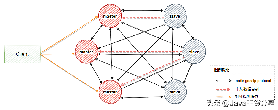
Figure 5-4
About gossip protocol
In the architecture described in Figure 5-4, other points are easy to understand, that is, what the gossip protocol is, which needs to be explained separately.
In the whole redis cluster architecture, if the following situations occur:
- Newly added node
- slot migration
- Node downtime
- slave is elected master
We hope that these changes can enable each node in the whole cluster to discover and propagate to the whole cluster as soon as possible, and all nodes in the cluster reach an agreement, then each node needs to be connected with each other and carry relevant status data for propagation,
According to the normal logic, broadcast is used to send messages to all nodes in the cluster. It is a bit that the data synchronization in the cluster is fast, but each message needs to be sent to all nodes, which consumes too much CPU and bandwidth. Therefore, the gossip protocol is used here.
The mission protocol is also called Epidemic Protocol. It has many aliases, such as "rumor algorithm", "epidemic propagation algorithm", etc.
Its characteristic is that in a network with a limited number of nodes, each node will "randomly" (not really random, but selecting communication nodes according to rules) communicate with some nodes. After some chaotic communication, the state of each node will be consistent within a certain time, as shown in Figure 5-5.
Suppose we set the following rules in advance:
1. Mission is a periodic message dissemination, which limits the period to 1 second
2. The infected node randomly selects k neighboring nodes (fan out) to spread the message. Here, set the fan out to 3 and spread the message to 3 nodes at most each time.
3. Each time a message is disseminated, a node that has not been sent is selected for dissemination
4. The node receiving the message will no longer broadcast to the sending node, such as A - > B. when B broadcasts, it will no longer send it to A.
There are 16 nodes in total. Node 1 is the initial infected node. Through the mission process, all nodes are finally infected:
Figure 5-5
Mission protocol message
The gossip protocol contains a variety of messages, including ping, pong, meet, fail, and so on.
ping: each node frequently sends pings to other nodes, including its own status and its own maintained cluster metadata, and exchanges metadata with each other through ping;
pong: ping and meet are returned, including their own status and other information. They can also be used for information broadcasting and updating;
Fail: after a node judges that another node fails, it sends a fail to other nodes to notify other nodes that the specified node is down.
Meet: a node sends a meet to a newly added node to join the cluster, and then the new node will start to communicate with other nodes. It is not necessary to send all CLUSTER MEET commands required to form a network. Send CLUSTER MEET message so that each node can reach other nodes. Each node only needs to pass through a known node chain. Since the gossip information will be exchanged in the heartbeat packet, the missing links between nodes will be created.
Advantages and disadvantages of mission
advantage: The advantage of gossip protocol is that metadata updates are scattered rather than concentrated in one place. Update requests will be sent to all nodes one after another. There is a certain delay in updating, which reduces the pressure; Decentralization, scalability, fault tolerance, consistent convergence, simplicity. It is not guaranteed that all nodes will receive messages at a certain time, but theoretically all nodes will eventually receive messages, so it is a final consistency protocol.
Disadvantages: Metadata update is delayed, which may lead to some lag in some operations of the cluster. Message delay, message redundancy.
Redis Cluster setup
The cluster needs at least 6 nodes (3 master and 3 slave mode). Each node can be built on the same machine or on different servers.
- 192.168.221.128 7000 , 7001
- 192.168.221.129 7002 , 7003
- 192.168.221.130 7004 , 7005
Start 6 nodes respectively.
- Under the redis installation directory, create the following directories respectively. These directories must be created in advance. Redis will not actively create these directories when it starts.
  mkdir -p /data/program/redis/run
  mkdir -p /data/program/redis/logs
  mkdir -p /data/program/redis/data/7000,7001
  mkdir -p /data/program/redis/conf
  mkdir -p /data/program/redis/redis-cluster
- Copy a copy of redis.conf to the redis cluster directory. Since there are only three machines, two redis servers need to be run on each machine. Therefore, the name of the redis.conf file needs to be modified to distinguish it_ 7000.conf. And modify the following contents of the file.
  pidfile "/data/program/redis/run/redis_7000.pid"   #pid storage directory
  logfile "/data/program/redis/logs/redis_7000.log"  #Log storage directory
  dir "/data/program/redis/data/7000"   #The data storage directory shall be created in advance
  cluster-enabled yes                   #Start cluster
  cluster-config-file nodes-7000.conf   #Cluster node configuration file, which cannot be edited manually. Ensure that the configuration files of each cluster node are different
  cluster-node-timeout 15000            #Timeout of cluster node, unit: ms. after timeout, the cluster will consider the node failed
- Each node needs to start two redis servers, so make a copy of the configuration file, and then modify the following configuration
  pidfile "/data/program/redis/run/redis_7001.pid"   #pid storage directory
  logfile "/data/program/redis/logs/redis_7001.log"  #Log storage directory
  dir "/data/program/redis/data/7001"   #The data storage directory shall be created in advance
  cluster-enabled yes                   #Start cluster
  cluster-config-file nodes-7001.conf   #Cluster node configuration file, which cannot be edited manually. Ensure that the configuration files of each cluster node are different
  cluster-node-timeout 15000            #Timeout of cluster node, unit: ms. after timeout, the cluster will consider the node failed
- Create two scripts for unified service running cluster-start.sh
  ./redis-server ../conf/redis_7000.conf
  ./redis-server ../conf/redis_7001.conf
cluster-shutdown.sh
pgrep redis-server | xargs -exec kill -9
Let the above script have execution permission through the following command
chmod +x cluster-*.sh
- The other two nodes repeat the above process to complete the startup of 6 nodes.
Configure redis cluster
After starting the five servers, you need to configure the cluster nodes through the following operations. In redis6.0, the cluster creation method is redis cli. The following commands can be executed on any server
Use the following command to create a cluster. The - cluster replica 1 parameter indicates that you want each master server to have a slave server. Here, it means 3 master and 3 slave. The machines with slave nodes created in this way cannot manually specify the master node. The redis cluster will try to assign the master and slave servers to different machines
[root@localhost bin]# ./redis-cli --cluster create 192.168.221.128:7000 192.168.221.128:7001 192.168.221.129 7002 192.168.221.129 7003 192.168.221.130 7004 192.168.221.130 7005 --cluster-replicas 1
After executing the above command, you will get the following execution results,
>>> Performing hash slots allocation on 6 nodes...
Master[0] -> Slots 0 - 5460
Master[1] -> Slots 5461 - 10922
Master[2] -> Slots 10923 - 16383
Adding replica 192.168.221.129:7003 to 192.168.221.128:7000
Adding replica 192.168.221.130:7005 to 192.168.221.129:7002
Adding replica 192.168.221.128:7001 to 192.168.221.130:7004
M: 36d34fd3985179786eeab50338e3972608df2f21 192.168.221.128:7000  #master
   slots:[0-5460] (5461 slots) master
S: 202028cfaf69fd5c8fcd5b7b75677d6963184ad9 192.168.221.128:7001
   replicates 124683446267c8910cd080238e72e3b1b589f41f
M: 5927296015093b9474fed5a354c4a04b9345e7a9 192.168.221.129:7002   #master
   slots:[5461-10922] (5462 slots) master
S: 089b77cb753c1ef62bd10f23230c38d4a0a64a09 192.168.221.129:7003
   replicates 36d34fd3985179786eeab50338e3972608df2f21
M: 124683446267c8910cd080238e72e3b1b589f41f 192.168.221.130:7004   #master
   slots:[10923-16383] (5461 slots) master
S: 82a9fe027179f197ff82547863c4252de8ba1354 192.168.221.130:7005
   replicates 5927296015093b9474fed5a354c4a04b9345e7a9
Can I set the above configuration? (type 'yes' to accept): yes
Two points can be seen from the above results:
- Pre allocate the slot interval of three nodes
- Automatically select the appropriate node as the master
View cluster status and other information
- cluster info view cluster status information
  [root@localhost bin]# ./redis-cli -p 7000
  127.0.0.1:7000> cluster info
  cluster_state:ok
  cluster_slots_assigned:16384
  cluster_slots_ok:16384
  cluster_slots_pfail:0
  cluster_slots_fail:0
  cluster_known_nodes:6
  cluster_size:3
  cluster_current_epoch:6
  cluster_my_epoch:1
  cluster_stats_messages_ping_sent:276
  cluster_stats_messages_pong_sent:262
  cluster_stats_messages_sent:538
  cluster_stats_messages_ping_received:257
  cluster_stats_messages_pong_received:276
  cluster_stats_messages_meet_received:5
  cluster_stats_messages_received:538
- View cluster node information
  127.0.0.1:7000> cluster nodes
  5927296015093b9474fed5a354c4a04b9345e7a9 192.168.221.129:7002@17002 master - 0 1626247374000 3 connected 5461-10922
  36d34fd3985179786eeab50338e3972608df2f21 192.168.221.128:7000@17000 myself,master - 0 1626247375000 1 connected 0-5460
  82a9fe027179f197ff82547863c4252de8ba1354 192.168.221.130:7005@17005 slave 5927296015093b9474fed5a354c4a04b9345e7a9 0 1626247376000 3 connected
  089b77cb753c1ef62bd10f23230c38d4a0a64a09 192.168.221.129:7003@17003 slave 36d34fd3985179786eeab50338e3972608df2f21 0 1626247375000 1 connected
  124683446267c8910cd080238e72e3b1b589f41f 192.168.221.130:7004@17004 master - 0 1626247376830 5 connected 10923-16383
  202028cfaf69fd5c8fcd5b7b75677d6963184ad9 192.168.221.128:7001@17001 slave 124683446267c8910cd080238e72e3b1b589f41f 0 1626247375000 5 connected
data distribution
In Redis Cluster, Sharding adopts the concept of slot, which is divided into 16384 slots, which is somewhat similar to the idea of pre sharding. Each key value pair entering Redis is hashed according to the key and allocated to one of the 16384 slots. The hash algorithm used is also relatively simple, that is, the module is taken after CRC16 [crc16(key)%16384].
Each node (node) in the Redis cluster is responsible for allocating part of the 16384 slots, that is, each slot corresponds to a node for processing.
As shown in Figure 5-6, suppose we have three master nodes: A, B and C. they can be three ports on one machine or three different servers. Then, if 16384 slots are allocated by hash slots, the slot intervals undertaken by their three nodes are:
- Node A covers 0-5000;
- Node B covers 5001-10000;
- Node C covers 10001-16383
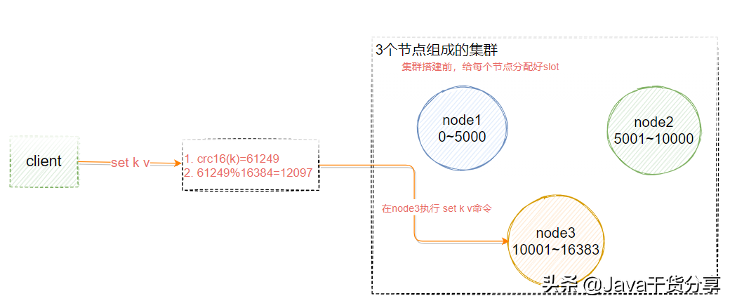
Figure 5-6
Client redirection
As shown in Figure 5-6, suppose that the key K should be stored on node3, and the user calls the set k v instruction on node1 or node2, how does the redis cluster handle it?
127.0.0.1:7291> set qs 1
(error) MOVED 13724 127.0.0.1:7293
The server returns MOVED, that is, the slot calculated according to the key is not managed by the current node. The server returns MOVED and tells the client to go to port 7293 for operation.
At this time, replace the port and use redis cli – p 7293 to return OK. Or use the command. / redis cli - C - P port. However, the problem is that the client needs to connect twice to complete the operation. Therefore, most redis clients maintain a corresponding relationship between slot and node locally. Before executing the instruction, first calculate the target node that the current key should be stored, and then connect to the target node for data operations.
The following commands are provided in the redis cluster to calculate which slot the current key should belong to
redis> cluster keyslot key1
High availability master-slave switching principle
If the master node does not have a slave node, the cluster will be unavailable when it fails.
Once a master node enters the FAIL state, the whole cluster will change to the FAIL state and trigger the failover mechanism. The purpose of failover is to select a new master node from the slave node so that the cluster can return to normal. This process is implemented as follows:
When a slave finds that its master is in the FAIL state, it attempts to Failover in order to become a new master. Because the suspended master may have multiple slaves, there is a process in which multiple slaves compete to become the master node. The process is as follows:
- slave finds that its master becomes FAIL
- Add 1 to the cluster currentEpoch recorded by yourself and broadcast FAILOVER_AUTH_REQUEST information
- When other nodes receive this information, only the master responds, judges the legitimacy of the requester, and sends FAILOVER_AUTH_ACK: only one ack is sent for each epoch
- Try to collect the failover returned by the master from the slave of the FAILOVER_AUTH_ACK
- After receiving ack s from more than half of the masters, the slave becomes a new Master (this explains why the cluster needs at least three Master nodes. If there are only two, when one of them hangs, only one Master node can not be elected successfully)
- Broadcast Pong messages to inform other cluster nodes.
The slave node does not attempt to initiate an election as soon as the master node enters the FAIL state, but there is a certain delay. A certain delay ensures that we wait for the FAIL state to spread in the cluster. If the slave attempts to vote immediately, other masters may not be aware of the FAIL state and may refuse to vote.
Delay calculation formula: DELAY = 500ms + random(0 ~ 500ms) + SLAVE_RANK * 1000ms
SLAVE_RANK indicates the rank of the total amount of data that this slave has copied from the master. The smaller the rank, the newer the replicated data. In this way, the slave with the latest data will initiate the election first
Analysis of common problems
Question: how to make relevant data fall on the same node?
For example, some multi key operations cannot cross nodes, such as the basic information and financial information of user 2673?
Add {hash tag} to the key. Redis will only obtain the string between {} when calculating the slot number for slot number calculation. In this way, because the strings in {} are the same because of the above two different keys, they can be calculated into the same slot
user{2673}base=...
user{2673}fin=...
The operation steps are as follows. The following key s will be saved in the same node.
127.0.0.1:7293> set a{qs}a 1
OK
127.0.0.1:7293> set a{qs}b 1
OK
127.0.0.1:7293> set a{qs}c 1
OK
127.0.0.1:7293> set a{qs}d 1
OK
127.0.0.1:7293> set a{qs}e 1
summary
advantage
- No central architecture.
- The data is stored and distributed in multiple nodes according to the slot. The data is shared among nodes, and the data distribution can be adjusted dynamically.
- Scalability: it can be linearly expanded to 1000 nodes (no more than 1000 are officially recommended), and nodes can be dynamically added or deleted.
- High availability. When some nodes are unavailable, the cluster is still available. By adding Slave as standby data copy, automatic failover can be realized. Status information is exchanged between nodes through gossip protocol, and the role promotion from Slave to Master is completed by voting mechanism.
- Reduce the operation and maintenance cost and improve the scalability and availability of the system.
Insufficient
- The implementation of the Client is complex. The driver requires the Smart Client to cache slots mapping information and update it in time, which improves the development difficulty. The immaturity of the Client affects the stability of the business.
- The node will be blocked for some reason (the blocking time is greater than the cluster node timeout), and it is judged to be offline. This kind of failover is not necessary.
- The data is replicated asynchronously, which does not guarantee the strong consistency of the data.
- When multiple businesses use the same set of clusters, they cannot distinguish hot and cold data according to statistics, and the resource isolation is poor, which is prone to mutual influence.
- Slave acts as a "cold standby" in the cluster, which can not relieve the reading pressure. Of course, the utilization of slave resources can be improved through the reasonable design of SDK.
Redistribution connection cluster
Modify the redisson.yml file and refer to the spring boot redis client example project
clusterServersConfig:
  nodeAddresses:
    - "redis://192.168.221.129:7003"
    - "redis://192.168.221.129:7002"
    - "redis://192.168.221.130:7004"

codec: !<org.redisson.codec.JsonJacksonCodec> {}
Note that the nodes corresponding to nodeaddress are all master s.
Codis
Codis is a distributed Redis solution. For upper tier applications, there is no obvious difference between connecting to the Codis Proxy and connecting to the native Redis Server (unsupported command list). Upper tier applications can be used like stand-alone Redis. The lower tier of Codis will handle request forwarding, non-stop data migration, etc,
Everything in the back is transparent to the front client. You can simply think that the back connected is a Redis service with unlimited memory.
codis architecture
As shown in Figure 5-7, it shows the overall architecture of Codis.
Codis Proxy: Redis proxy service for client connection, which implements Redis protocol. Except that some commands are not supported (list of unsupported commands), the performance is no different from that of native Redis (like tweetproxy). For the same business cluster, multiple Codis Proxy instances can be deployed simultaneously; The CODIS dashboard ensures that the status of different CODIS proxies is the same
codis-redis-group: Represents a redis service cluster node. A RedisGroup has a Master and multiple Slave nodes
ZooKeeper: Codis relies on ZooKeeper to store the meta information of data routing table and Codis proxy node. The commands initiated by Codis config will be synchronized to each surviving Codis proxy through ZooKeeper
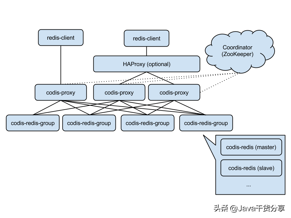
Figure 5-7