1, Register introduction
Register, according to Baidu Encyclopedia, register is an integral part of the CPU. Registers are high-speed storage components with limited storage capacity. They can be used to temporarily store instructions, data and addresses.
Generally speaking, registers store things. What we store is just from our objective things to instructions, data or addresses.
GPIO
brief introduction
GPIO (general purpose IO ports), that is, general input and output ports. A GPIO port needs at least two registers, one is the "general IO port control register" for control, and the other is the "general I/O port data register" for storing data. Each bit of the data register corresponds to the hardware pin of GPIO, and the data transmission direction is set through the control register. The data flow direction of each bit pin can be set through the control register.
Working mode of GPIO
1. Floating input GPIO_IN_FLOATING - floating input, which can be used for KEY identification, RX1 2. GPIO with pull-up input_ IPU - IO internal pull-up resistor input
3. GPIO with pull-down input_ IPD - IO internal pull-down resistance input
4. Analog input GPIO_AIN - apply ADC analog input or save power under low power consumption
5. Open drain output GPIO_OUT_OD - IO output 0 is connected to GND, IO output 1 is suspended, and external pull-up resistance is required to realize output high level. When the output is 1, the state of the IO port is pulled high by the pull-up resistance, but because it is in the open drain output mode, the IO port can also be changed from the external circuit to the low level or unchanged. The IO input level change can be read to realize the IO bidirectional function of C51
6. Push pull output GPIO_OUT_PP - IO output 0 - connected to GND, IO output 1 - connected to VCC, the read input value is unknown
7. Push pull output GPIO with multiplexing function_ AF_ PP - on-chip and off-chip functions (SCL and SDA of I2C)
8. Open drain output GPIO with multiplexing function_ AF_ Od - on chip and off chip functions (TX1,MOSI,MISO.SCK.SS)
2, Assembly language light LED
LED0 EQU 0x42218194
RCC_APB2ENR EQU 0x40021018
;GPIOA_CRH EQU 0x40010804
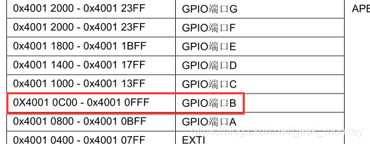
GPIOB_CRL EQU 0x40010C00
Stack_Size EQU 0x00000400
AREA STACK, NOINIT, READWRITE, ALIGN=3
Stack_Mem SPACE Stack_Size
__initial_sp
AREA RESET, DATA, READONLY
__Vectors DCD __initial_sp
DCD Reset_Handler
AREA |.text|, CODE, READONLY
THUMB
REQUIRE8
PRESERVE8
ENTRY
Reset_Handler
BL LED_Init
MainLoop BL LED_ON
BL Delay
BL LED_OFF
BL Delay
B MainLoop
LED_Init
PUSH {R0,R1, LR}
LDR R0,=RCC_APB2ENR
ORR R0,R0,#0x08
LDR R1,=RCC_APB2ENR
STR R0,[R1]
LDR R0,=GPIOB_CRL
BIC R0,R0,#0XFF0FFFFF
LDR R1,=GPIOB_CRL
STR R0,[R1]
LDR R0,=GPIOB_CRL
ORR R0,R0,#0X00300000
LDR R1,=GPIOB_CRL
STR R0,[R1]
MOV R0,#1
LDR R1,=LED0
STR R0,[R1]
POP {R0,R1,PC}
LED_ON
PUSH {R0,R1, LR}
MOV R0,#0
LDR R1,=LED0
STR R0,[R1]
POP {R0,R1,PC}
LED_OFF
PUSH {R0,R1, LR}
MOV R0,#1
LDR R1,=LED0
STR R0,[R1]
POP {R0,R1,PC}
Delay
PUSH {R0,R1, LR}
MOVS R0,#0
MOVS R1,#0
MOVS R2,#0
DelayLoop0
ADDS R0,R0,#1
CMP R0,#330
BCC DelayLoop0
MOVS R0,#0
ADDS R1,R1,#1
CMP R1,#330
BCC DelayLoop0
MOVS R0,#0
MOVS R1,#0
ADDS R2,R2,#1
CMP R2,#15
BCC DelayLoop0
POP {R0,R1,PC}
END
3, C language lights up the LED
Delay function Delay.h
void  Delay()
{
     unsigned  int  i;
     while(t--)
         for (i=0;i<10000000;i++);
}
Lighting function Light.h
//A lamp
void A_LED(){
	GPIOA_ORD=0x0<<5;		//PA5 low level
	GPIOB_ORD=0x1<<6;		//PB6 high level
	GPIOC_ORD=0x1<<7;		//PC7 high level
}
//B lamp
void B_LED(){
	GPIOA_ORD=0x1<<5;		//PA5 high level
	GPIOB_ORD=0x0<<6;		//PB6 low level
	GPIOC_ORD=0x1<<7;		//PC7 high level
}
//C lamp
void C_LED(){
	GPIOA_ORD=0x1<<5;		//PA5 high level
	GPIOB_ORD=0x1<<6;		//PB6 high level
	GPIOC_ORD=0x0<<7;		//PC7 low level
}
Main function
#include"Delay.h"
#include"Light.h"
#define RCC_AP2ENR 	* ((unsigned volatile int*)0x40021018)//APB2 enable clock register
#define GPIOA_CRL 	* ((unsigned volatile int*)0x40010800) / / configure gpioa register
#define	GPIOA_ORD	*((unsigned volatile int*)0x4001080C)
#define GPIOB_CRH 	* ((unsigned volatile int*)0x40010C04) / / configure gpiob register
#define	GPIOB_ORD	*((unsigned volatile int*)0x40010C0C)
#define GPIOC_CRH 	* ((unsigned volatile int*)0x40011004)//GPIOC configuration register
#define	GPIOC_ORD	*((unsigned volatile int*)0x4001100C)

//Main function
int main()
{
	int j=100;
	RCC_AP2ENR|=1<<2;			//APB2-GPIOA peripheral clock enable
	RCC_AP2ENR|=1<<3;			//APB2-GPIOB peripheral clock enable
	RCC_AP2ENR|=1<<4;			//APB2-GPIOC peripheral clock enable
	//These two lines of code can be combined into RCC_ APB2ENR|=1<<3|1<<4;
	GPIOA_CRL&=0x0FFFFFFF;		//Set bit reset
	GPIOA_CRL|=0x20000000;		//PA7 push pull output
	GPIOA_ORD|=1<<5;			//Set PA5 initial light to off

	GPIOB_CRH&=0xFFFFFF0F;		//Set bit reset
	GPIOB_CRH|=0x00000020;		//PB6 push pull output
	GPIOB_ORD|=1<<6;			//Set the initial light to off

	GPIOC_CRH&=0x0FFFFFFF;		//Set bit reset
	GPIOC_CRH|=0x30000000;   	//PC7 push pull output
	GPIOC_ORD|=0x1<<7;			//Set the initial light to off
	while(j)
	{
		A_LED();
		Delay();
		B_LED();
		Delay();
		C_LED();
		Delay();
	}
}
Compile and build to generate. HEX files. For the creation of projects and subsequent operations, please refer to the author's previous blog
Creation of STM32 project in Keil5 MDK version
Burning program
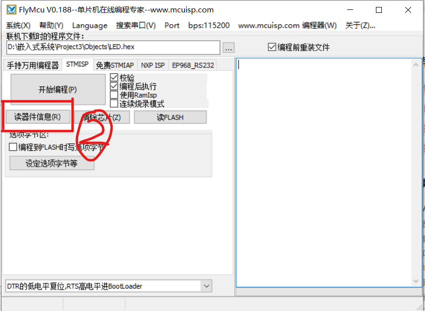
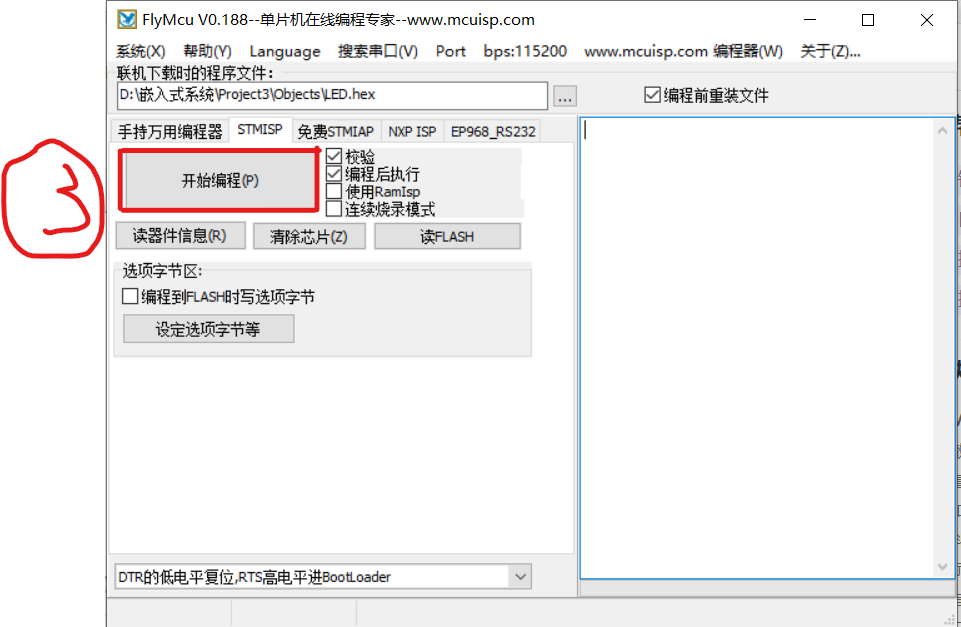
You can burn directly with Keil5 or FlyMcu.
- Open the program, click three small dots and import the generated. HEX file
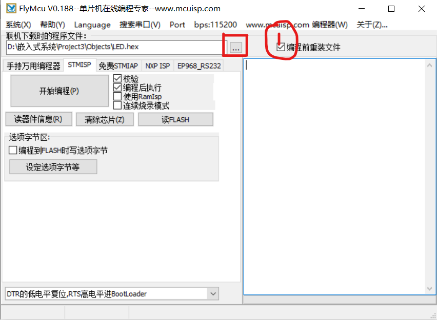
- Read device information
- Start programming
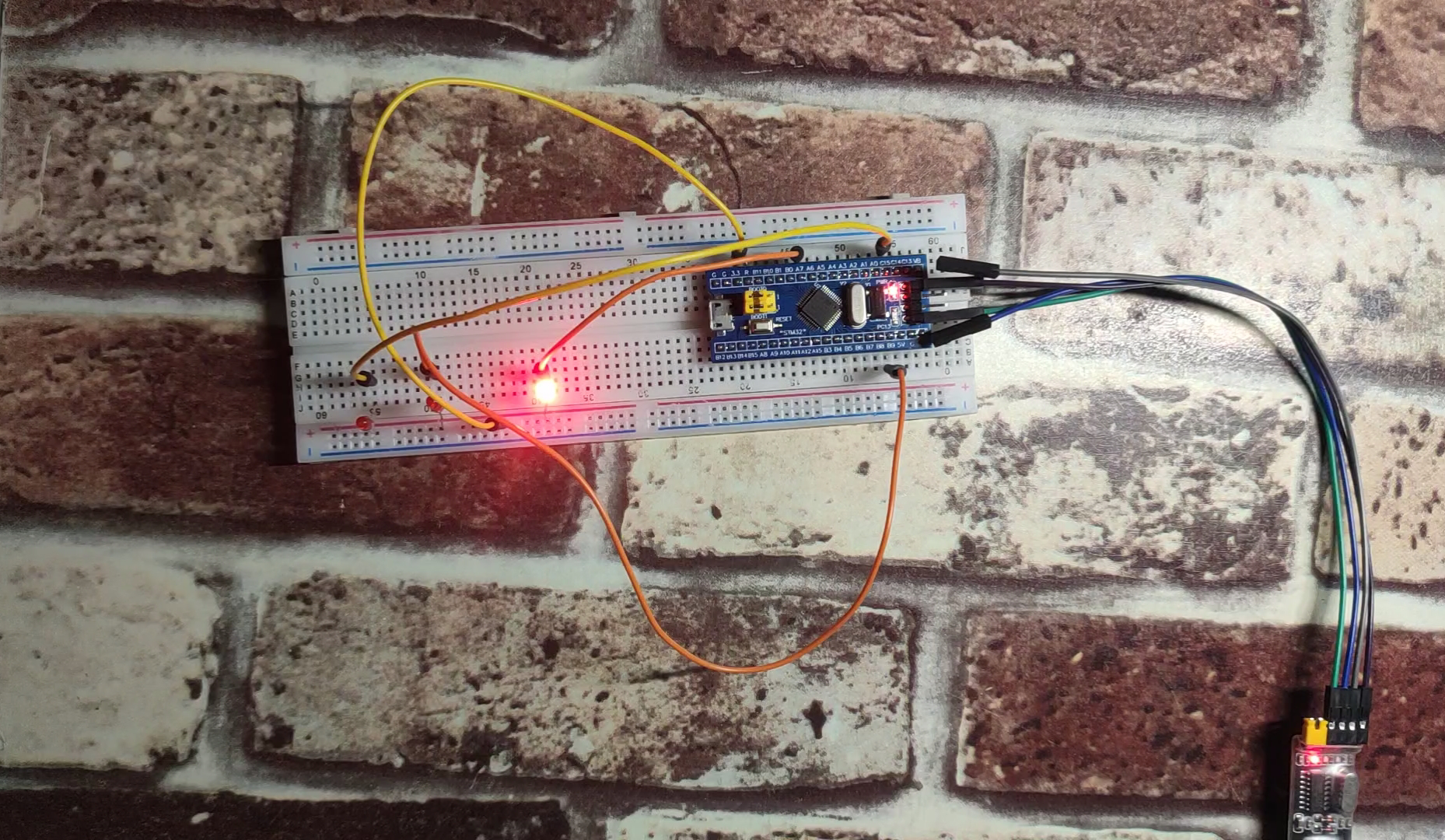
4, Build physical object
The connection process is self operated. Since the editor did not take photos when connecting, the specific process can be viewed online.
Connection physical drawing
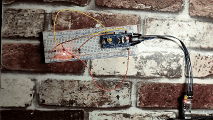
- Operation results
5, Summary
Generally speaking, it is not difficult to develop some simple functions with STM32, but because the author is developing with hardware for the first time, he doesn't understand many things. It can be said that he learns while doing. I now believe more that "nothing is difficult in the world, as long as you are willing to climb".
6, Reference articles
STM32F103C8T6 realizes running water lamp
STM32 register introduction, address search, and direct operation register
STM32 from address to register