catalogue
1. Basic principle of Zhang's calibration method
1.3 internal parameters of camera
1.4 external parameters of camera
2.1 feature point detection and target coordinate initialization
1. Basic principle of Zhang's calibration method
1.1 camera pinhole model
First, we know the camera model established by pinhole model. Suppose that the homogeneous coordinates of the camera's two-dimensional phase plane are expressed as , the homogeneous coordinates of the three-dimensional world coordinate system are expressed as
 . The relationship between the camera phase coordinate system and the world coordinate system is as follows:

Where s is the scale factor, Represents the external parameter matrix, R and t represent the rotation matrix and translation matrix, which represents the relationship between the camera coordinate system and the world coordinate system. A is the internal parameter matrix of the camera,
 Coordinates of the main point, α and β Is the scale factor of u-axis and v-axis of phase coordinate system, γ A parameter that represents the tilt of two image axes. To facilitate processing, the external parameter matrix is further expressed as:
For the sake of generality, assuming that the target is located on the world coordinate system Z=0, then Column removed,
 Remove Z from.
1.2 homography matrix H
We set 3 × Homography matrix of 3
Then the corresponding relationship of the points on the target in the phase plane (image) is:

After considering the scale factor, the homography matrix can be re expressed as:

It should be noted that since the target data we prepared is known (world coordinate system coordinates) and the corresponding phase plane coordinates can be obtained by image processing algorithm, H can be obtained, i.e Are known.
1.3 internal parameters of camera
Homography matrix H has 8 degrees of freedom and 6 external parameters (3 for rotation and 3 for translation), so we can only obtain two constraints on internal parameters. Using the properties of rotation matrix, we can obtain these two constraints.
Properties of rotation matrix
1. The rotation matrix is orthogonal, and the dot product of any two columns is 0
2. Each component of the rotation matrix is a unit vector, and the sum of the squares of the three terms is 1
The resulting constraints are:


order

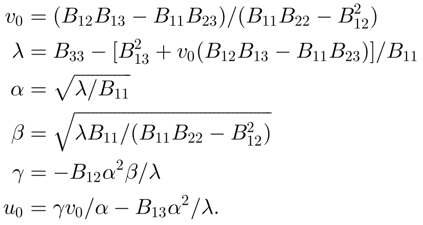
Then the B matrix can be solved by using the above constraints, and (closed form solution of B) the camera internal parameters can be solved according to the corresponding set of equations as follows:
1.4 external parameters of camera
After we get the A matrix from the previous step, it is easier to find the external parameters
It can be seen that there are the following corresponding relationships:

Combined with property 2 of rotation matrix, we can get
Considering the noise, the exact rotation matrix may not be obtained, and the consistent rotation matrix needs to be obtained by singular value decomposition.
1.5 optimization parameters
The solution of M obtained in the above steps is obtained by minimizing an algebraic distance without physical significance. We can improve it by maximum likelihood estimation. The literature gives n images of a phase plane with m points on the phase plane. It is assumed that the noise of image points is independent and evenly distributed. The maximum likelihood estimation can be obtained by minimizing the following function:

Among them, Is in the i-th image
 The rotation matrix R can be transformed into a rotation vector (angular axis) through Rodriguez formula. This is a nonlinear minimization problem, which can be solved by Levenberg Marquardt algorithm. It is worth noting that the radial distortion of the lens is considered in this process.
1.6 summary
Zhang Zhengyou's camera calibration procedure is as follows:
1. Print the pattern and attach it to the plane.
2. Take some images of the model plane in different directions by moving the plane or camera.
3. Detect the feature points in the image.
4. The closed form solution is used to estimate five internal parameters and all external parameters.
5. Refine all parameters, including lens distortion parameters, through maximum likelihood estimation.
In practical application, after we prepare the target and take images for the target, the main work content is 3-5 steps
2.OpenCV implementation
2.1 feature point detection and target coordinate initialization
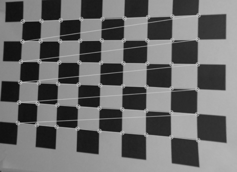
For different calibration targets, the feature point detection methods are different. OpenCV recommends using the pattern of the chess board as the calibration target and the corner of the square as the feature point. Therefore, only the detection methods based on the target are listed here.
After inputting an image, provide the size of the chessboard (the number of corners in the chessboard). Call the findChessboardCorners function to return the positions of all chessboard corners. Note that the return value of this function is Boolean.
CV_EXPORTS_W bool findChessboardCorners(
InputArray image, //Contains an 8-bit grayscale or color pattern of a checkerboard image
Size patternSize, //Size of pattern (number of rows and rows of inner corners)
OutputArray corners,//An array that outputs detected corners
int flags = CALIB_CB_ADAPTIVE_THRESH + CALIB_CB_NORMALIZE_IMAGE );
After calling this function, the pixel coordinates of the detected corners will be stored in the corresponding parameters of OutputArray corners. In order to improve the corner accuracy to the sub-pixel level, you can further call the find4QuadCornerSubpix function. Note that the first parameter of this function should input an 8-bit gray image. The third parameter is the size of the corner search window.
//! finds subpixel-accurate positions of the chessboard corners
CV_EXPORTS_W bool find4QuadCornerSubpix( InputArray img, InputOutputArray corners, Size region_size );
We can call drawchess board corners to draw corners in the chessboard image and connect them with lines (the connection order is the storage order of corners in the vector).
CV_EXPORTS_W void drawChessboardCorners( InputOutputArray image, Size patternSize,
                                         InputArray corners, bool patternWasFound );
Examples of corner detection and display of a single image are as follows:
#include "opencv2/opencv.hpp"
#include "fstream"
#include "iostream"
using namespace std;
using namespace cv;
void main(){
ifstream fin("calibdata.txt"); /* The path of the image file used for calibration */
std::vector<cv::Point2f> imageCorners;
cv::Size boardSize(9, 6);
cv::Mat image; // to contain chessboard image
std::string filename;
std::getline(fin, filename);
// Open the image
image = cv::imread(filename);

// Get the chessboard corners
bool found = cv::findChessboardCorners(image, // image of chessboard pattern
	boardSize,                        // size of pattern
	imageCorners);                    // list of detected corners

// Get subpixel accuracy on the corners
if (found) {
	Mat view_gray;
	cvtColor(image, view_gray, COLOR_RGB2GRAY);
	cv::find4QuadCornerSubpix(view_gray, imageCorners, cv::Size(11, 11));
		//Draw the corners
		cv::drawChessboardCorners(view_gray, boardSize, imageCorners,1);
		cv::namedWindow("Detected points");
		cv::imshow("Detected points", view_gray);
		cv::waitKey(0);
  }
}
In order to detect more corners and improve the calibration accuracy, more photos of the same pattern need to be taken from different angles. In order to accept the corner coordinates of different pictures, we use the vector container nested container to save the corner coordinates. The container type is implemented by the template instantiated by OpenCV.
// (each square is one unit)
std::vector<std::vector<cv::Point3f> > objectPoints;
// the image point positions in pixels
std::vector<std::vector<cv::Point2f> > imagePoints;
The next work is to put the corners collected from each picture into the container one by one and write a circular program.
After obtaining the image coordinates, we also need to initialize the target coordinate system. For simplicity, we initialize the target coordinate system coordinates in the unit of block length. (we establish the world coordinate system on the target)
// 3D Scene Points:
// Initialize the chessboard corners
// in the chessboard reference frame
// The corners are at 3D location (X,Y,Z)= (i,j,0)
for (int i = 0; i < boardSize.height; i++) {
	for (int j = 0; j < boardSize.width; j++) {

			objectCorners.push_back(cv::Point3f(i, j, 0.0f));
	}
}
So far, we have obtained the phase plane coordinates and the corresponding target coordinate system coordinates, and passed them into two containers. Next, we can calculate the internal and external parameters by using the calibrateCamera function provided by OpenCV.
2.2 camera calibration
Before calling calibrateCamera, we need to understand its definition to prepare the corresponding parameters.
CV_EXPORTS_W double calibrateCamera(
InputArrayOfArrays objectPoints,//Data of target coordinate system points
InputArrayOfArrays imagePoints, //Data of image points
Size imageSize,//Image size
InputOutputArray cameraMatrix, //Output internal parameter matrix
InputOutputArray distCoeffs,//Output distortion matrix
OutputArrayOfArrays rvecs, //Output rotation matrix
OutputArrayOfArrays tvecs,//Output translation matrix
int flags = 0, //set an option
TermCriteria criteria = TermCriteria(
TermCriteria::COUNT + TermCriteria::EPS, 30, DBL_EPSILON) );
Thus, we need to prepare four parameters to receive the calibration results.
cv::Mat cameraMatrix = Mat(3, 3, CV_32FC1, Scalar::all(0)); /* Camera internal parameter matrix */
cv::Mat distCoeffs = Mat(1, 5, CV_32FC1, Scalar::all(0)); /* Five distortion coefficients of camera: k1,k2,p1,p2,k3 */
std::vector<Mat> tvecsMat;  /* Rotation vector of each image */
std::vector<Mat> rvecsMat; /* Translation vector of each image */
Note that the flag parameter can set the following functions as required: (refer to the translation of old dream bloggers here)
CV_CALIB_USE_INTRINSIC_GUESS: when using this parameter, there should be estimated values of fx, fy, U0 and V0 in the cameraMatrix matrix matrix. Otherwise, the center point of the image will be initialized (u0,v0) and the least square will be used to estimate fx and fy.
CV_CALIB_FIX_PRINCIPAL_POINT: the optical axis point will be fixed during optimization. When CV_ CALIB_ USE_ INTRINSIC_ When the guess parameter is set, the optical axis point will remain in the center or an input value.
CV_CALIB_FIX_ASPECT_RATIO: fix the ratio of fx/fy, and take fy as a variable for optimization calculation. When CV_CALIB_USE_INTRINSIC_GUESS is not set, fx and fy will be ignored. Only the ratio fx/fy will be used in the calculation.
CV_CALIB_ZERO_TANGENT_DIST: set the tangential distortion parameters (p1,p2) to zero.
CV_CALIB_FIX_K1,…,CV_CALIB_FIX_K6: the corresponding radial distortion remains unchanged in the optimization.
CV_CALIB_RATIONAL_MODEL: calculate k4, k5 and k6 distortion parameters. If it is not set, only the other 5 distortion parameters are calculated.
Enter the prepared parameters into the function.
2.3 result evaluation
After obtaining the internal and external parameters of the camera, re calculate the projection of the corner points on the target, that is, back projection, and then calculate the deviation between the projection coordinates and the actual coordinates, so as to evaluate the accuracy of the calibration results. The backprojection function provided by OpenCV is projectPoints()
CV_EXPORTS_W
void projectPoints(
InputArray objectPoints,//Coordinates of corner points on target coordinate system
InputArray rvec, //Rotation matrix
InputArray tvec, //translation matrix
InputArray cameraMatrix,//Camera matrix
InputArray distCoeffs,//Camera distortion coefficient
OutputArray imagePoints,//Back projection point coordinates
OutputArray jacobian = noArray(),
double aspectRatio = 0 );
Each picture calls the function to calculate the norm between the back projection point coordinates and the actual coordinates, and the resulting error is accumulated to obtain the re projection error. The use example is as follows. The code here is extracted from the Opencv Zhang Zhengyou camera calibration fool tutorial of Makino blogger.
//Evaluate the calibration results
	cout << "Start evaluation of calibration results\n";
	double total_err = 0.0; /* The sum of the average errors of all images */
	double err = 0.0; /* Average error per image */
	vector<Point2f> image_points2; /* Save the recalculated projection points */
	cout << "\t Calibration error of each image:\n";
	fout << "Calibration error of each image:\n";
	for (i = 0; i < image_count; i++)
	{
		vector<Point3f> tempPointSet = object_points[i];
		/* Through the internal and external parameters of the camera, the three-dimensional points in the space are re projected and calculated to obtain new projection points */
		projectPoints(tempPointSet, rvecsMat[i], tvecsMat[i], cameraMatrix, distCoeffs, image_points2);
		/* Calculate the error between the new projection point and the old projection point*/
		vector<Point2f> tempImagePoint = image_points_seq[i];
		Mat tempImagePointMat = Mat(1, tempImagePoint.size(), CV_32FC2);
		Mat image_points2Mat = Mat(1, image_points2.size(), CV_32FC2);
		for (int j = 0; j < tempImagePoint.size(); j++)
		{
			image_points2Mat.at<Vec2f>(0, j) = Vec2f(image_points2[j].x, image_points2[j].y);
			tempImagePointMat.at<Vec2f>(0, j) = Vec2f(tempImagePoint[j].x, tempImagePoint[j].y);
		}
		err = norm(image_points2Mat, tempImagePointMat, NORM_L2);
		total_err += err /= point_counts[i];
		std::cout << "The first" << i + 1 << "Average error of images:" << err << "pixel" << endl;
		fout << "The first" << i + 1 << "Average error of images:" << err << "pixel" << endl;
	}
	std::cout << "Overall average error:" << total_err / image_count << "pixel" << endl;
	fout << "Overall average error:" << total_err / image_count << "pixel" << endl << endl;
	std::cout << "Evaluation completed!" << endl;
2.4 removing image distortion
We note that after calibration, the distortion coefficient is also obtained. We can use the distortion coefficient and the camera internal and external parameter data to remove the distortion, so that all images taken by the calibrated camera will not have distortion. We can call initUndistortRectifyMap() to calculate the distortion map and remap() to apply the obtained map to the image.
CV_EXPORTS_W
void initUndistortRectifyMap(
InputArray cameraMatrix, //Camera matrix
InputArray distCoeffs, //Distortion coefficient
InputArray R, //Optional
InputArray newCameraMatrix,//Matrix for generating distortion removal
Size size, //Size after distortion removal
int m1type, //Output mapping type
OutputArray map1, OutputArray map2);//x and y mapping functions

CV_EXPORTS_W
void remap(
InputArray src, //Input original image
OutputArray dst,//Image after distortion removal
InputArray map1, InputArray map2,//x and y mapping functions
int interpolation,//Interpolation method (see #InterpolationFlags)
int borderMode = BORDER_CONSTANT,//Pixel extrapolation method (see #BorderTypes)
const Scalar& borderValue = Scalar());//Constant boundary value, 0 by default
Use examples are as follows:
// remove distortion in an image (after calibration)
cv::Mat remap(const cv::Mat& image, cv::Size& outputSize) {

cv::Mat undistorted;

if (outputSize.height == -1) {
		outputSize = image.size();}

if (mustInitUndistort) { // called once per calibration

  // dist = distCoeffs;

  cv::initUndistortRectifyMap(
			cameraMatrix,  // computed camera matrix
			distCoeffs,    // computed distortion matrix
			cv::Mat(),     // optional rectification (none)
			cv::Mat(),     // camera matrix to generate undistorted
			outputSize,    // size of undistorted
			CV_32FC1,      // type of output map
			map1, map2);   // the x and y mapping functions

		mustInitUndistort = false;
	}

	// Apply mapping functions
	cv::remap(image, undistorted, map1, map2,
		cv::INTER_LINEAR); // interpolation type

	return undistorted;
}
// Exampple of Image Undistortion
std::cout << filelist[5] << std::endl;
image = cv::imread(filelist[5], 0);
cv::Size newSize(static_cast<int>(image.cols * 1.5), static_cast<int>(image.rows * 1.5));
cv::Mat uImage = remap(image, newSize);
2.5 summary
In general, Zhang Zhengyou calibration method based on OpenCV mainly includes the following steps:
1. Prepare pictures for calibration
2. Extract feature point coordinates
3. Get the coordinates of the world coordinate system
4. Camera calibration
5. Result evaluation
6. Remove distortion
3. References
[1]Z. Zhang, "A flexible new technique for camera calibration," in IEEE Transactions on Pattern Analysis and Machine Intelligence, vol. 22, no. 11, pp. 1330-1334, Nov. 2000, doi: 10.1109/34.888718.
[2]Opencv Zhang Zhengyou camera calibration fool tutorial_ Makino's blog - CSDN blog_ opencv camera calibration
https://blog.csdn.net/dcrmg/article/details/52929669
[3]OpenCV learning notes (VII) function understanding and learning of camera calibration_ Bouncing blog - CSDN blog
https://blog.csdn.net/xuxunjie147/article/details/79219774
[4]OpenCV 3 Computer Vision Application Programming Cookbook - Third Edition,Robert Laganiere,February 2017,Packt Publishing,ISBN: 9781786469717