When writing the structure of LED lamp, you need to set the clock of GPIO port, input and output mode and high and low levels of GPIO pin.
Next, we will introduce how to configure each structure
- Introduction to GPIO
General purpose input / output is referred to as GPIO for short. STM32F103VET6 has 80 gpios in total. These IO pins are divided into groups A, B, C, D and E, with 0 ~ 15 pins in each group. The basic state of these pins can be controlled by software, such as high and low level of pins, input and output state, etc. However, before using the GPIO pin, it needs to be set, mainly including peripheral clock setting, input / output mode setting and pin rate setting.
(1) Peripheral clock settings use library function RCC_APB2PeriphClockCmd(), for example, set group A pins in GPIO, and the code is as follows:
RCC_APB2PeriphClockCmd(RCC_APB2Periph_GPIOB,ENABLE)
(2) Input / output mode, pin rate setting
Pin input / output mode and pin rate can be set through a structure in the firmware library, and the structure code is as follows;
typedef struct
{
   uint16_t GPIO_Pin;
   GPIOSpeed_TypeDef GPIO_Speed;
   GPIOMode_TypeDef GPIO_Mode;
}GPIO_InitTypeDef;
The input and output modes of pins are as follows:
Analog input GPIO_AIN - apply ADC analog input or save power under low power consumption;
Floating input GPIO_IN_FLOATING - floating input, which can be used for KEY identification;
GPIO with pull-up input_ IPU - IO internal pull-up resistance input;
GPIO with pull-down input_ IPD - IO internal pull-down resistance input;
Open drain output GPIO_OUT_OD - IO output 0 connected to GND, IO output 1, suspended;
Push pull output GPIO_OUT_PP - IO output 0 - connected to GND, IO output 1 - connected to VCC;
Push pull output GPIO with multiplexing function_ AF_ PP -- on-chip and off-chip functions (SCL and SDA of I2C);
Open drain output GPIO with multiplexing function_ AF_ Od -- on-chip and off-chip functions.
2.LED lamp control principle
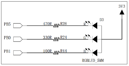
The connection between the LED lamp and the GPIO pin is shown in the figure below. PB0, PB1 and PB5 are the 0, 1 and 5 pins of GPIO group B in STM32F103VET respectively. You only need to set PB0, PB1 and PB5 to low level to turn on the corresponding LED lamp.
3. Macro definition of parameters
(1) Macro definition of LED lamp pin
#include "stm32f10x.h"
#define LED_G_GPIO_PIN         GPIO_PIN_0
#define LED_G_GPIO_PORT        GPIOB
#define LED_G_GOIO_CLK         RCC_APB2Periph_GPIOB

#define LED_B_GPIO_PIN                GPIO_PIN_1
#define LED_B_GPIO_PORT       GPIOB
#define LED_B_GPIO_CLK        RCC_APB2Periph_GPIOB

#define LED_R_GPIO_PIN                GPIO_PIN_5
#define LED_R_GPIO_PORT       GPIOB
#define LED_R_GPIO_CLK        RCC_APB2Periph_GPIOB

#define     ON    1
#define     OFF   0
(2) Macro definition of LED light on and off state
#define     LED_G(a)   if(a)\
          GPIO_SetBits(LED_G_GPIO_PORT,LED_G_GPIO_PIN);\
  else  GPIO_ResetBits(LED_G_GPIO_PORT,LED_G_GPIO_PIN);
void LED_GPIO_Config(void);

#define     LED_B(a)   if(a)\
          GPIO_SetBits(LED_B_GPIO_PORT,LED_B_GPIO_PIN);\
  else  GPIO_ResetBits(LED_B_GPIO_PORT,LED_B_GPIO_PIN);
void LED_GPIO_Config(void);

#define     LED_R(a)   if(a)\
          GPIO_SetBits(LED_R_GPIO_PORT,LED_R_GPIO_PIN);\
  else  GPIO_ResetBits(LED_R_GPIO_PORT,LED_R_GPIO_PIN);
void LED_GPIO_Config(void);
Selective GPIO using macro with parameters_ Setbits() and GPIO_ResetBits() function, which are the setting functions of pin high and low levels defined in the firmware library.
(3)LED_ Initialization of GPIO
Use the above macro to write the initialization function of LED lamp. The code is as follows:
void LED_GPIO_Config(void)
{
    GPIO_InitTypeDef   GPIO_InitStruct;
    RCC_APB2PeriphClockCmd(LED_G_GOIO_CLK|LED_B_GOIO_CLK|LED_R_GOIO_CLK,ENABLE);
    GPIO_InitStruct.GPIO_Pin = LED_G_GPIO_PIN_0;
    GPIO_InitStruct.GPIO_Mode = GPIO_Mode_Out_PP;
    GPIO_InitStruct.GPIO_Speed = GPIO_Speed_50MHz;
    GPIO_Init(LED_G_GPIO_PORT, &GPIO_InitStruct);

    GPIO_InitTypeDef   GPIO_InitStruct;
    RCC_APB2PeriphClockCmd(LED_B_GOIO_CLK,ENABLE);
    GPIO_InitStruct.GPIO_Pin = LED_B_GPIO_PIN_1;
    GPIO_Init(LED_B_GPIO_PORT, &GPIO_InitStruct);

    GPIO_InitTypeDef   GPIO_InitStruct;
    RCC_APB2PeriphClockCmd(LED_R_GOIO_CLK,ENABLE);
    GPIO_InitStruct.GPIO_Pin = LED_R_GPIO_PIN_5;
    GPIO_Init(LED_R_GPIO_PORT, &GPIO_InitStruct);

    GPIO_SetBits(LED_G_GPIO_PORT, macLED1_GPIO_PIN);
  GPIO_SetBits(LED_B_GPIO_PORT, macLED2_GPIO_PIN);
  GPIO_SetBits(LED_R_GPIO_PORT, macLED3_GPIO_PIN);
}
(4) Main function call
In the main function, call the LED_ previously defined. GPIO_ Config initializes the control pin of the LED, and then directly calls various macros to control the LED light on and off to realize the control of the LED light.
int main(void)
{

  LED_GPIO_Config();  //Initialize GPIO
  while (1)
  {
      LED1( ON );
      Delay(0x0FFFFF);
      LED1( OFF );

      LED2( ON );
      Delay(0x0FFFFF);
      LED2( OFF );

      LED3( ON );
      Delay(0x0FFFFF);
      LED3( OFF );
  }
}- give the thumbs-up
- Write answers
- Collection
-
share
- Invitation answer
- Put away