order
Words written in the front: This article is long, read patiently
UAV021 (I) This paper implements STM32F429 porting FreeRTOS system, on the basis of which IIC communication is realized and 10DOF data is read. In flight control, it refers to three-axis acceleration, three-axis angular velocity, three-axis magnetic force and one axis air pressure. These 10 sets of data are the core data of flight control, and their importance is self-evident.
Here, MPU6050 is used to measure acceleration and angular velocity, HMC5883 magnetometer and MS5611 barometer; IIC communication is used to read data.
In this paper, IIC communication protocol and implementation will be implemented first, then MPU6050 principle and data reading, HMC5883 principle and data reading, MS5611 principle and data reading respectively. There are many details in this article. I hope you will not only copy the code, but gradually understand it.
Code package download link (no Gitee account should be registered): https://gitee.com/gengstrong/UAV021/raw/master/UAV021_2-IIC_10DOF_MPU6050_HM5883_MS5611.zip
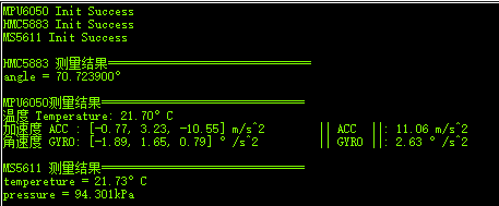
The code is compiled under Keil and passes the test. The final running result is as follows:
Finally, before writing the text, please allow me to make complaints about it. There are also codes for these sensors on the Internet, but either they need to be downloaded by points (I haven't seen how they are written in them), or they are poorly typeset, with few comments and poor readability. Both the domestic open source mentality and the quality of open source need to be improved. Therefore, this article will try to solve the above problems, of course, there may be many shortcomings, please correct!
1, IIC communication protocol and Implementation
1.1 seven basic operations
IIC communication protocol uses two signal lines SCL and SDA for level combination, and defines seven basic operations: start, end, reply, non reply, wait for reply, send one byte, receive one byte.
1. Start: SCL is 1, SDA jumps from 1 to 0.
void IIC_Start(void)
{
	SDA_OUT();     			// SDA output mode
	IIC_SDA = 1;
	IIC_SCL = 1;			// SCL is 1
	delay_us(4);
 	IIC_SDA = 0;			// Start: SDA from 1 to 0
	delay_us(4);
	IIC_SCL = 0;			//Clamp I2C bus and prepare to send or receive data
}
Some of them are defined in the header file as follows:
#define SDA_IN()  {GPIOH->MODER&=~(3<<(5*2));GPIOH->MODER|=0<<5*2;}	//PH5 input mode
#define SDA_OUT() {GPIOH->MODER&=~(3<<(5*2));GPIOH->MODER|=1<<5*2;} //PH5 output mode

#define IIC_SCL   PHout(4) //SCL
#define IIC_SDA   PHout(5) //SDA
#define READ_SDA  PHin(5)  //Input SDA
2. End: SCL is 1, SDA jumps from 0 to 1.
It can be seen that when the SCL is 1, the SDA is not allowed to change at will, otherwise the start signal or the end signal will be generated, which is also the reason why the SCL=0 after the command (except the end).
void IIC_Stop(void)
{
	SDA_OUT();
	IIC_SCL = 0;
	IIC_SDA = 0;
 	delay_us(4);
	IIC_SCL = 1;
	IIC_SDA = 1;
	delay_us(4);
}
3. Reply: the meaning of reply is that after receiving a byte sent by the host, the host releases the SDA, and the slave pulls the SDA down (0) to indicate that the byte has been received.
void IIC_Ack(void)
{
	IIC_SCL = 0;
	SDA_OUT();
	IIC_SDA = 0;		// SDA is 0 -- answer
	delay_us(2);
	IIC_SCL = 1;
	delay_us(2);
	IIC_SCL = 0;
}
4. Non response: I think non response is a bad translation and easy to be misunderstood. "Reply" is to pull down SDA (0), "reply not" is to pull up SDA (1), in fact, it is also to receive data.
void IIC_NAck(void)
{
	IIC_SCL = 0;
	SDA_OUT();
	IIC_SDA = 1;		// SDA is 1 -- no response
	delay_us(2);
	IIC_SCL = 1;
	delay_us(2);
	IIC_SCL = 0;
}
What are the connections and differences between response and non response? The first detail of IIC: "reply" and "non reply" are replies to the host after receiving data from the slave. "Reply" indicates that there is data to be transmitted next, "non reply" indicates that it is the last data, so it is not necessary to continue transmission.
For example, if the host sends one byte, then the slave will send a "non response" signal after reading it; if the host wants to send three bytes in succession, then the first two bytes will be sent, and the slave needs "response", and the third needs "non response".
The second detail of IIC needs to be explained by the way: the host refers to the device that sends data, and the slave refers to the device that receives data. For example, if STM32 reads MPU6050 data, then MPU6050 is the host and STM32 is the slave. After MPU6050 sends data, STM32 needs to make a reply (Ack or NAck).
5. Wait for response: after the host sends a data, it will wait for a while to see whether the slave pulls down the SDA, that is, to see whether the slave makes an Ack reply or a NAck reply. If the slave pulls down the SDA (answer Ack) and can continue to transmit data, the next Byte cannot be transmitted unless it is restarted.
uint8_t IIC_WaitAck(void)
{
	uint8_t cnt = 0;
	SDA_IN();      			//SDA set as input
	IIC_SDA = 1;
	delay_us(1);
	IIC_SCL = 1;
	delay_us(1);
	while (READ_SDA)		// Read SDA and exit from the slave answering 0
	{
		cnt ++;
		if (cnt>250)
		{
			IIC_Stop();		// Timeout exit
			return 1;
		}
	}
	IIC_SCL = 0;
	return 0;
}
6. Send a byte. In the process of sending bytes, 1 has 0, SCL needs to be 0, otherwise it will become a start / end signal.
However, there is also a problem that the SCL is always 0. For example, when the SDA is always 1 in a period of time, how can we know how many 1s are contained in it? Is it one, two or three? So this is the third detail of IIC: when sending bytes, SCL also plays the role of clock. An SCL pulse reads SDA once, which means that there is a bit of SDA data. Look at the picture more directly:
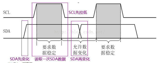
It can be seen that when the SCL is 0, the SDA becomes 0 / 1, and then the SCL is pulled up to read the SCL data; after reading, the SCL is pulled down first, and then the SDA is changed.
void IIC_SendByte(uint8_t txd)
{
    uint8_t t;
	SDA_OUT();
    IIC_SCL=0;						// Pull down the clock before data transmission
    for (t=0; t<8; t++)
    {
		IIC_SDA = (txd&0x80)>>7; 	// Transmit the highest bit
		txd <<= 1; 	  				// Move left one bit
		delay_us(2);   				// All three delays are necessary for TEA5767
		IIC_SCL = 1;				// Pull up SCL to read data
		delay_us(2);
		IIC_SCL = 0;				// Lower the clock to prepare for next bit transmission
		delay_us(2);
    }
}
7. receive a byte. Receiving a byte is the process of reading SDA.
uint8_t IIC_RecvByte(void)
{
	uint8_t i, recv=0;
	SDA_IN();							// SDA set as input
	for(i=0; i<8; i++ )
	{
		IIC_SCL = 0;
		delay_us(2);
		IIC_SCL = 1;
		if(READ_SDA)					// Read 1, move recv left 1 bit and add 1
		{
			recv <<= 1;
			recv += 0x01;
		}
		else							// Read 0, move recv left 1 bit and add 0
		{
			recv <<= 1;
			recv += 0x00;
		}
		delay_us(1);
	}
    return recv;
}
These are the seven basic operations of IIC:
| operation | Corresponding function |
|---|---|
| start | IIC_Start() |
| end | IIC_Stop() |
| answer | IIC_Ack() |
| Non response | IIC_NAck() |
| Waiting for response | IIC_WaitAck() |
| Send a byte | IIC_SendByte() |
| Receive a byte | IIC_RecvByte() |
This section also describes three details of IIC:
- "Reply" and "non reply" are replies to the host after receiving data from the slave. The "reply" indicates that there is data to be transmitted next. The "non reply" indicates that it is the last data, so it is unnecessary to continue transmission.
- Host refers to the device that sends data, and slave refers to the device that receives data.
- When sending bytes, SCL also acts as a clock. SDA is read once in an SCL pulse, which means there is one bit of SDA data.
Of course, there are other details. Let's talk about them later.
1.2 several combined operations
IIC protocol defines the above seven basic, which can be used more easily through combination. For example, after sending data, you often have to wait for the response signal, and after receiving data, you also have to reply. Based on this, the following functions (3 writes, 3 reads) are defined for ease of use. Note that all function definitions have certain rules. Proper nouns are capitalized and initials are capitalized. I hope we can have a unified style.
| Function name | Function function |
|---|---|
| uint8_t IIC_WriteByte(uint8_t txd); | Send a byte and + wait for reply |
| uint8_t IIC_WriteAddrRegByte(uint8_t addr, uint8_t reg, uint8_t dat); | Write a given data in the given register of a given device |
| uint8_t IIC_WriteAddrRegBytes(uint8_t addr, uint8_t reg, uint8_t len, uint8_t *buf); | Write multiple given data in given register of given device |
| uint8_t IIC_ReadByte(uint8_t ack); | IIC reads a byte + answer / no answer |
| uint8_t IIC_ReadAddrRegByte(uint8_t addr, uint8_t reg); | Read a data in a given register of a given device |
| uint8_t IIC_ReadAddrRegBytes(uint8_t addr, uint8_t reg, uint8_t len, uint8_t *buf); | Read out multiple data in a given register of a given device |
Each function is implemented as follows. If it is not very urgent, it is suggested that we should knock it once again, feel the rules, take the essence and remove the dross.
j next, the iic.h and iic.c files are given directly as follows:
#ifndef _MYIIC_H
#define _MYIIC_H
#include "sys.h"

/* For convenience, first put some macro definitions here	*/
#define SDA_IN()  {GPIOH->MODER&=~(3<<(5*2));GPIOH->MODER|=0<<5*2;}	//PH5 input mode
#define SDA_OUT() {GPIOH->MODER&=~(3<<(5*2));GPIOH->MODER|=1<<5*2;} //PH5 output mode

#define IIC_SCL   PHout(4) //SCL
#define IIC_SDA   PHout(5) //SDA
#define READ_SDA  PHin(5)  //Input SDA

#define IIC_GPIO   GPIOH
#define IIC_PIN    GPIO_PIN_4 | GPIO_PIN_5
#define IIC_ENCLK() __HAL_RCC_GPIOH_CLK_ENABLE()

/*	IIC Basic operation method	*/
void IIC_Init(void);                				// Initialize IO port of IIC

void IIC_Start(void);								// Send IIC start signal
void IIC_Stop(void);	  							// Send IIC stop signal
void IIC_Ack(void);									// IIC sends ACK signal
void IIC_NAck(void);								// IIC sends NACK signal
void IIC_SendByte(uint8_t txd);						// IIC sends a byte (without waiting for reply)
uint8_t IIC_RecvByte(void);							// IIC receives a byte (no reply)
uint8_t IIC_WaitAck(void); 							// IIC waiting for ACK signal

/*	IIC Combined operation method	*/
uint8_t IIC_WriteByte(uint8_t txd);														// IIC sends a byte (with waiting response)
uint8_t IIC_WriteAddrRegByte(uint8_t addr, uint8_t reg, uint8_t dat);					// Write a given data in the given register of a given device
uint8_t IIC_WriteAddrRegBytes(uint8_t addr, uint8_t reg, uint8_t len, uint8_t *buf); 	// Write multiple given data in given register of given device

uint8_t IIC_ReadByte(uint8_t ack);														// IIC reads a byte
uint8_t IIC_ReadAddrRegByte(uint8_t addr, uint8_t reg);									// Read a data in a given register of a given device
uint8_t IIC_ReadAddrRegBytes(uint8_t addr, uint8_t reg, uint8_t len, uint8_t *buf);		// Read out multiple data in a given register of a given device

#endif
/* 1. Understanding of host and slave: the sender is the host, for example, STM32 reads MPU data, MPU sends data, and MPU is the host																		*/
/* 2. Understanding of reply: reply is to release SDA to make slave reply after master transmits data. The slave function pulls down SDA to 0, which is called response and non response														*/
/*    Do you want to answer? This is determined by the host. For example, read 6 consecutive Byte data of MPU6050, the first 5 need to answer, and the sixth need not 														*/
/* 3. SCL When it is 1, SDA should not jump randomly, because jumping from low to high means the end, and jumping from high to low means the end. When the SCL is 0, the data will be changed, so the SCL must be 0 when transmitting data											*/
/*	  But why not always 0? Because it's always 0, it's unknown whether it's one or two or even three consecutive zeros after reading SDA as 0. Therefore, an SCL is read once, which is similar to clock function. An SCL pulse has an SDA data	*/
/* 4. IIC The address has 7-bit address and 8-bit address. 8-bit address is actually 7-bit address shifted left by one bit. The 7-bit address of MPU6050 is 0x68, the actual read data address is 0x68 < < 1, and the write data address is 0x68 < < 1 | 0x01				*/
/*    Another example is that the 7-bit address of HMC5883 is 0x77, the 8-bit write address is 0x77 < < 1 = 0xEE, and the 8-bit read address is 0x77 < < 1 | 0x01 = 0xef. This is also the reason why some place bits 0x77 and some place bits 0xEE				*/

#include "iic.h"
#include "delay.h"

/****************************** IIC Hardware initialization***********************************/

/* IIC Hardware initialization 		*/
/* See IIC for pin definition_ PIN 	*/
void IIC_Init(void)
{
	GPIO_InitTypeDef  GPIO_InitStructure;				// GPIO initialization structure
	IIC_ENCLK();										// Enable IIC clock

	GPIO_InitStructure.Pin 		= IIC_PIN;
	GPIO_InitStructure.Mode 	= GPIO_MODE_OUTPUT_PP;	// Push pull output
	GPIO_InitStructure.Speed 	= GPIO_SPEED_FAST;		// 100MHz
	GPIO_InitStructure.Pull 	= GPIO_PULLUP;			// Pull up
	HAL_GPIO_Init(IIC_GPIO, &GPIO_InitStructure);		// initialization

	IIC_SCL = 1;
	IIC_SDA = 1;
}

/****************************** IIC Basic operation method***********************************/
/* IIC Start signal			*/
/* SCL=1 SDA from 1 to 0	*/
void IIC_Start(void)
{
	SDA_OUT();     			// SDA output mode
	IIC_SDA = 1;
	IIC_SCL = 1;			// SCL is 1
	delay_us(4);
 	IIC_SDA = 0;			// Start: SDA from 1 to 0
	delay_us(4);
	IIC_SCL = 0;			//Clamp I2C bus and prepare to send or receive data
}

/* Generate IIC stop signal		*/
/* SCL=1 SDA from 0 to 1	*/
void IIC_Stop(void)
{
	SDA_OUT();
	IIC_SCL = 0;
	IIC_SDA = 0;
 	delay_us(4);
	IIC_SCL = 1;
	IIC_SDA = 1;
	delay_us(4);
}

/* Wait for the answer signal 							*/
/* Normal response from slave, SDA = 0						*/
/* Return value: 0, reply received						*/
/*        1,No response received, corresponding to Article 2 of start note	*/
uint8_t IIC_WaitAck(void)
{
	uint8_t cnt = 0;
	SDA_IN();      			//SDA set as input
	IIC_SDA = 1;
	delay_us(1);
	IIC_SCL = 1;
	delay_us(1);
	while (READ_SDA)		// Read SDA and exit from the slave answering 0
	{
		cnt ++;
		if (cnt>250)
		{
			IIC_Stop();		// Timeout exit
			return 1;
		}
	}
	IIC_SCL = 0;
	return 0;
}

/* Generate ACK response			*/
/* Pull down SDA to indicate response		*/
void IIC_Ack(void)
{
	IIC_SCL = 0;
	SDA_OUT();
	IIC_SDA = 0;		// SDA is 0 -- answer
	delay_us(2);
	IIC_SCL = 1;
	delay_us(2);
	IIC_SCL = 0;
}

/* Generate ACK response			*/
/* Pull SDA up to indicate non response	*/
void IIC_NAck(void)
{
	IIC_SCL = 0;
	SDA_OUT();
	IIC_SDA = 1;		// SDA is 1 -- no response
	delay_us(2);
	IIC_SCL = 1;
	delay_us(2);
	IIC_SCL = 0;
}

/* IIC Send a byte (no response waiting)*/
void IIC_SendByte(uint8_t txd)
{
    uint8_t t;
	SDA_OUT();
    IIC_SCL=0;						// Pull down the clock before data transmission
    for (t=0; t<8; t++)
    {
		IIC_SDA = (txd&0x80)>>7; 	// Transmit the highest bit
		txd <<= 1; 	  				// Move left one bit
		delay_us(2);   				// All three delays are necessary for TEA5767
		IIC_SCL = 1;				// Pull up SCL to read data
		delay_us(2);
		IIC_SCL = 0;				// Lower the clock to prepare for next bit transmission
		delay_us(2);
    }
}

/* Receive 1 byte				*/
/* Return parameter: bytes received		*/
uint8_t IIC_RecvByte(void)
{
	uint8_t i, recv=0;
	SDA_IN();							// SDA set as input
	for(i=0; i<8; i++ )
	{
		IIC_SCL = 0;
		delay_us(2);
		IIC_SCL = 1;
		if(READ_SDA)					// Read 1, move recv left 1 bit and add 1
		{
			recv <<= 1;
			recv += 0x01;
		}
		else							// Read 0, move recv left 1 bit and add 0
		{
			recv <<= 1;
			recv += 0x00;
		}
		delay_us(1);
	}
    return recv;
}

/****************************** IIC Combined operation method***********************************/

/* IIC Send a byte											*/
/* Return whether the slave responds, equivalent to IIC_SendByte() + IIC_WaitAck()	*/
/* ack=0 It means response, ack=1 means no response!!!						*/
uint8_t IIC_WriteByte(uint8_t txd)
{
    uint8_t ack;
	IIC_SendByte(txd);
	ack = IIC_WaitAck();			// Wait for the slave to answer, t=0 for answer, t=1 for no answer!!!
	return ack;
}

/* IIC Send a byte in the specified device specified register					*/
/* Return whether the slave responds or not										*/
/* 0 Indicates response (sending succeeded), 1 indicates no response (sending failed)!!!	*/
uint8_t IIC_WriteAddrRegByte(uint8_t addr, uint8_t reg, uint8_t dat)
{
	IIC_Start();
	if (IIC_WriteByte(addr))
	{
		IIC_Stop();
		return 1;
	}
	if (IIC_WriteByte(reg))
	{
		IIC_Stop();
		return 1;
	}
	if (IIC_WriteByte(dat))
	{
		IIC_Stop();
		return 1;
	}
	IIC_Stop();
	return 0;
}

/* IIC Send a byte in the specified device specified register					*/
/* Return whether the slave responds or not										*/
/* 0 Indicates response (sending succeeded), 1 indicates no response (sending failed)!!!	*/
uint8_t IIC_WriteAddrRegBytes(uint8_t addr, uint8_t reg, uint8_t len, uint8_t *buf)
{
	uint8_t i;
	IIC_Start();
	if (IIC_WriteByte(addr))
	{
		IIC_Stop();
		return 1;
	}
	if (IIC_WriteByte(reg))
	{
		IIC_Stop();
		return 1;
	}
	for (i=0; i<len; i++)
	{
		if (IIC_WriteByte(buf[i]))
		{
			IIC_Stop();
			return 1;
		}
	}
	IIC_Stop();
	return 0;
}

/* Read 1 byte, equivalent to IIC_RecvByte() + IIC_(N)Ack()				    */
/* ack=0 Send ACK; ack=1, send NACK (no intentional anti logic, see Note 2 at the beginning for the reason) */
/* Return bytes read													*/
uint8_t IIC_ReadByte(uint8_t ack)
{
	uint8_t recv = 0;
	recv = IIC_RecvByte();
    if (ack)
        IIC_NAck();						// ack=1 send nACK
    else
        IIC_Ack(); 						// ack=0 send ACK
    return recv;
}

/* Read a data in a given register of a given device	*/
uint8_t IIC_ReadAddrRegByte(uint8_t addr, uint8_t reg)
{
	uint8_t recv;
	IIC_Start();
	IIC_WriteByte(addr);
	IIC_WriteByte(reg);

	IIC_Start();
	IIC_WriteByte(addr | 0x01);
	recv = IIC_ReadByte(1);				// NAck
	IIC_Stop();
	return recv;
}

/* Read out multiple data in a given register of a given device	*/
uint8_t IIC_ReadAddrRegBytes(uint8_t addr, uint8_t reg, uint8_t len, uint8_t *buf)
{
	uint8_t i;
	IIC_Start();
	if (IIC_WriteByte(addr))
	{
		IIC_Stop();
		return 1;
	}
	IIC_WriteByte(reg);

	IIC_Start();
	IIC_WriteByte(addr | 0x01);
	for (i=0; i<len; i++)
	{
		if (i == len-1)
			buf[i] = IIC_ReadByte(1);	// Last byte NAck
		else
			buf[i] = IIC_ReadByte(0);	// Ack when not the last byte
	}
	IIC_Stop();
	return 0;
}
2, MPU6050 related knowledge and data reading
2.1 MPU6050 related knowledge
First of all, MPU means Micro Processor Unit. Compared with Micro Control Unit (MCU), MPU is good at data processing. In fact, there are already logic units in MPU6050, which can read the data of accelerometer and gyroscope and process them, such as low-pass filtering, and finally send them through IIC protocol.
Another popular saying is that accelerometers are used to obtain acceleration, needless to say, gyroscopes are used to obtain angular velocity.
Now look directly at the schematic. In general, the MPU6050 on the market leads to the following pins:
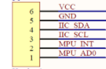
The description of each pin is illustrated by the diagram of the positive point atom as follows:
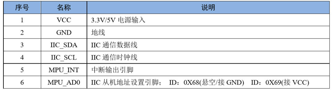
The first four don't need to be mentioned, the fifth MPU_INT is the interrupt pin of MPU6050, which can be configured as roll, shake, touch, etc., but it is rarely used in flight control. 6th MPU_AD0 is used to configure IIC slave address, but I don't quite understand why this function is added. Is it to be able to access two MPU6050?
Let's skip this question for the moment. Let's take a look at a question about the address 0x86 (assumed to be in the air). IIC has 7-bit address and 8-bit address difference. 0x68 = 0110 1000 is actually a 7-bit address, 0x68 < 1 | 0 = 1101 0000 = 0xD0 is a write address, 0x68 < 1 | 1 = 1101 0001 = 0xD1 is a read address. Both 0xD0 and 0xD1 are 8-bit addresses. In fact, 0x68 moves one bit left and adds 0 (write address) or 1 (read address). So if you see 0xD0, don't be surprised, it's just the definition of 8-bit address. In fact, the high 7 bits represent the device and the lowest 1 bit represents the read / write operation.
2.2 data reading and conversion
(1) When reading MPU6050, the data read by acceleration and gyroscope are 16 bits (2 bytes), and the range is - 32767 ~ 32767. In this case, the stored variable is defined as bit short type. Short is also called short int. unlike int, short is 2 bytes, while int is 4 bytes. 65535 is a positive number for int types, but - 1 for short types. Therefore, we must pay attention to this point when reading MPU6050 data.
(2) So what is the relationship between the read data and the real data? This is related to the FSR (Full Scale Range) of the initial configuration. For accelerometers, the initial range can be configured as ± 2g, ± 4g, ± 8g and ± 16g, and G is the acceleration of gravity. If the configuration is ± 2g, reading to - 32767 represents - 2g, and reading to 32767 represents 2g. The conversion formula is:
True acceleration = read data * 2g / 32767Gyroscope is similar to acceleration, and its range can be configured as ± 250 ° / s2, ± 500 ° / s2, ± 1000 ° / s2, ± 2000 ° / s2. For example, ± 2000 ° / s2 range is adopted, and the relationship between the real angular velocity and the data read is as follows:
True angular velocity = read data * 2000 / 32767 (in ° / s^2 ^)2.3 procedure
The program includes mpu6050.h, mpu6050.c and main.c. Although main.c uses the operating system, it is easy to call without OS. If you still have difficulties, you can comment and leave a message. I will try to get a version that does not use OS.
// mpu6050.h mainly includes the definition of MPU6050 register and some user operations

#ifndef __MPU6050_H
#define __MPU6050_H
#include "iic.h"

/************************** MPU6050 Register definition******************************/

#define MPU6050_ADDR				0X68<<1	// AD0 is grounded, 7-bit IIC address is 0x68; AD0 is connected to V3.3, 7-bit IIC address is 0x69. 8-bit address shift left one bit

#define MPU6050_SELF_TESTX_REG		0X0D	//Self check register X
#define MPU6050_SELF_TESTY_REG		0X0E	//Self check register Y
#define MPU6050_SELF_TESTZ_REG		0X0F	//Self check register Z
#define MPU6050_SELF_TESTA_REG		0X10	//Self check register A
#define MPU6050_SAMPLE_RATE_REG		0X19	//Sampling frequency divider
#define MPU6050_CFG_REG				0X1A	//Configuration register
#define MPU6050_GYRO_CFG_REG		0X1B	//Gyroscope configuration register
#define MPU6050_ACCEL_CFG_REG		0X1C	//Accelerometer configuration register
#define MPU6050_MOTION_DET_REG		0X1F	//Motion detection threshold setting register
#define MPU6050_FIFO_EN_REG			0X23	//FIFO enable register
#define MPU6050_I2CMST_CTRL_REG		0X24	//IIC host control register
#define MPU6050_I2CSLV0_ADDR_REG	0X25	//IIC slave 0 device address register
#define MPU6050_I2CSLV0_REG			0X26	//IIC slave 0 data address register
#define MPU6050_I2CSLV0_CTRL_REG	0X27	//IIC slave 0 control register
#define MPU6050_I2CSLV1_ADDR_REG	0X28	//IIC slave 1 device address register
#define MPU6050_I2CSLV1_REG			0X29	//IIC slave 1 data address register
#define MPU6050_I2CSLV1_CTRL_REG	0X2A	//IIC slave 1 control register
#define MPU6050_I2CSLV2_ADDR_REG	0X2B	//IIC slave 2 device address register
#define MPU6050_I2CSLV2_REG			0X2C	//IIC slave 2 data address register
#define MPU6050_I2CSLV2_CTRL_REG	0X2D	//IIC slave 2 control register
#define MPU6050_I2CSLV3_ADDR_REG	0X2E	//IIC slave 3 device address register
#define MPU6050_I2CSLV3_REG			0X2F	//IIC slave 3 data address register
#define MPU6050_I2CSLV3_CTRL_REG	0X30	//IIC slave 3 control register
#define MPU6050_I2CSLV4_ADDR_REG	0X31	//IIC slave 4 device address register
#define MPU6050_I2CSLV4_REG			0X32	//IIC slave 4 data address register
#define MPU6050_I2CSLV4_DO_REG		0X33	//IIC slave 4 write data register
#define MPU6050_I2CSLV4_CTRL_REG	0X34	//IIC slave 4 control register
#define MPU6050_I2CSLV4_DI_REG		0X35	//IIC slave 4 read data register

#define MPU6050_I2CMST_STA_REG		0X36	//IIC host status register
#define MPU6050_INTBP_CFG_REG		0X37	//Interrupt / bypass setting register
#define MPU6050_INT_EN_REG			0X38	//Interrupt enable register
#define MPU6050_INT_STA_REG			0X3A	//Interrupt status register

#define MPU6050_ACCEL_XOUTH_REG		0X3B	//Acceleration value, X-axis high 8-bit register
#define MPU6050_ACCEL_XOUTL_REG		0X3C	//Acceleration value, X-axis low 8-bit register
#define MPU6050_ACCEL_YOUTH_REG		0X3D	//Acceleration value, Y-axis high 8-bit register
#define MPU6050_ACCEL_YOUTL_REG		0X3E	//Acceleration value, Y-axis low 8-bit register
#define MPU6050_ACCEL_ZOUTH_REG		0X3F	//Acceleration value, Z-axis high 8-bit register
#define MPU6050_ACCEL_ZOUTL_REG		0X40	//Acceleration value, Z-axis low 8-bit register

#define MPU6050_TEMP_OUTH_REG		0X41	//Temperature value high octet register
#define MPU6050_TEMP_OUTL_REG		0X42	//Temperature value low 8-bit register

#define MPU6050_GYRO_XOUTH_REG		0X43	//Gyroscope value, X-axis high 8-bit register
#define MPU6050_GYRO_XOUTL_REG		0X44	//Gyroscope value, X-axis low 8-bit register
#define MPU6050_GYRO_YOUTH_REG		0X45	//Gyroscope value, Y-axis high 8-bit register
#define MPU6050_GYRO_YOUTL_REG		0X46	//Gyroscope value, Y-axis low 8-bit register
#define MPU6050_GYRO_ZOUTH_REG		0X47	//Gyroscope value, Z-axis high 8-bit register
#define MPU6050_GYRO_ZOUTL_REG		0X48	//Gyroscope value, Z-axis low 8-bit register

#define MPU6050_I2CSLV0_DO_REG		0X63	//IIC slave 0 data register
#define MPU6050_I2CSLV1_DO_REG		0X64	//IIC slave 1 data register
#define MPU6050_I2CSLV2_DO_REG		0X65	//IIC slave 2 data register
#define MPU6050_I2CSLV3_DO_REG		0X66	//IIC slave 3 data register

#define MPU6050_I2CMST_DELAY_REG	0X67	//IIC host delay management register
#define MPU6050_SIGPATH_RST_REG		0X68	//Signal channel reset register
#define MPU6050_MDETECT_CTRL_REG	0X69	//Motion detection control register
#define MPU6050_USER_CTRL_REG		0X6A	//User control register
#define MPU6050_PWR_MGMT1_REG		0X6B	//Power management register 1
#define MPU6050_PWR_MGMT2_REG		0X6C	//Power management register 2
#define MPU6050_FIFO_CNTH_REG		0X72	//FIFO count register high octet
#define MPU6050_FIFO_CNTL_REG		0X73	//FIFO count register low octet
#define MPU6050_FIFO_RW_REG			0X74	//FIFO read write register
#define MPU6050_DEVICE_ID_REG		0X75	//Device ID register

/**************************** Operation function********************************/

uint8_t MPU6050_Init(void); 				//Initialize MPU60506050
uint8_t MPU6050_SetGyroFsr(uint8_t fsr);
uint8_t MPU6050_SetAccelFsr(uint8_t fsr);
uint8_t MPU6050_SetLPF(uint16_t lpf);
uint8_t MPU6050_SetRate(uint16_t rate);

float MPU6050_GetTemperature(void);
uint8_t MPU6050_GetGyroscope(float *gx, float *gy, float *gz);
uint8_t MPU6050_GetAccelerometer(float *ax, float *ay, float *az);

/************************** User defined management*****************************/

enum MPU6050_GYRO_FSR								// Full Scale Range
{
	MPU6050_GYRO_FSR_250 = 0,
	MPU6050_GYRO_FSR_500 = 1,
	MPU6050_GYRO_FSR_1000 = 2,
	MPU6050_GYRO_FSR_2000 = 3
};

enum MPU6050_ACCEL_FSR
{
	MPU6050_ACCEL_FSR_2g = 0,
	MPU6050_ACCEL_FSR_4g = 1,
	MPU6050_ACCEL_FSR_8g = 2,
	MPU6050_ACCEL_FSR_16g = 3
};


#define GYRO_FSR			MPU6050_GYRO_FSR_2000	// Accelerometer range ± 2000 (optional MPU6050_GYRO_FSR enumeration)
#define ACCEL_FSR			MPU6050_ACCEL_FSR_2g	// Accelerometer range ± 2g (optional MPU6050_ACCEL_FSR enumeration)
#define MPU_RATE			50						// Sampling rate 50Hz (optional 4-2000Hz)

#endif
// mpu6050.c initializes MPU6050 and reads and transforms related data

#include "mpu6050.h"
#include "sys.h"
#include "delay.h"
#include "usart.h"

/* Initialize MPU6050 	*/
/* Return value: 0, success		*/
/* Other, error code		*/
uint8_t MPU6050_Init(void)
{
	uint8_t res;
	res = IIC_WriteAddrRegByte(MPU6050_ADDR, MPU6050_PWR_MGMT1_REG, 0x80);		// Reset MPU6050
	if (res)
	{
		printf("MPU6050 Reset failed \r\n");
		return 1;
	}
	delay_ms(100);
	IIC_WriteAddrRegByte(MPU6050_ADDR, MPU6050_PWR_MGMT1_REG, 0x00);	 		// Wake up MPU6050

	MPU6050_SetGyroFsr(GYRO_FSR);												// Gyroscope sensor
	MPU6050_SetAccelFsr(ACCEL_FSR);												// Acceleration sensor
	MPU6050_SetRate(MPU_RATE);													// Set the sampling rate 50Hz (optional 4-2000Hz)
	IIC_WriteAddrRegByte(MPU6050_ADDR, MPU6050_INT_EN_REG, 0X00);				// Turn off all interrupts
	IIC_WriteAddrRegByte(MPU6050_ADDR, MPU6050_USER_CTRL_REG, 0X00);			// I2C main mode off
	IIC_WriteAddrRegByte(MPU6050_ADDR, MPU6050_FIFO_EN_REG, 0X00);				// Close FIFO
	IIC_WriteAddrRegByte(MPU6050_ADDR, MPU6050_INTBP_CFG_REG,0X80);				// INT pin low level valid
	res = IIC_ReadAddrRegByte(MPU6050_ADDR, MPU6050_DEVICE_ID_REG);				// Read device ID
	if(res == (MPU6050_ADDR >> 1))												// Device ID is correct
	{
		IIC_WriteAddrRegByte(MPU6050_ADDR, MPU6050_PWR_MGMT1_REG, 0X01);		//Set CLKSEL,PLL X axis as reference
		IIC_WriteAddrRegByte(MPU6050_ADDR, MPU6050_PWR_MGMT2_REG, 0X00);		//Acceleration and gyroscope work
		MPU6050_SetRate(MPU_RATE);												//Set the sampling rate to 50Hz
 	}
	else
	{
		printf("MPU6050 Init failed \r\n");
		return 1;
	}
	printf("MPU6050 Init Success \r\n");
	return 0;
}


/* Set MPU6050 gyroscope sensor full range					*/
/* fsr:0,±250dps;1,±500dps;2,±1000dps;3,±2000dps	*/
/* Return value: 0, set successfully									*/
/*    Other, setting failed 									*/

uint8_t MPU6050_SetGyroFsr(uint8_t fsr)
{
	return IIC_WriteAddrRegByte(MPU6050_ADDR, MPU6050_GYRO_CFG_REG, fsr<<3);	//Set the full range of gyroscope
}

/* Set MPU60506050 acceleration sensor full range	*/
/* fsr:0,±2g;1,±4g;2,±8g;3,±16g		*/
/* Return value: 0, set successfully						*/
/*    Other, setting failed 						*/

uint8_t MPU6050_SetAccelFsr(uint8_t fsr)
{
	return IIC_WriteAddrRegByte(MPU6050_ADDR, MPU6050_ACCEL_CFG_REG, fsr<<3);	//Set acceleration sensor full range
}

/* Set the digital low pass filter of MPU60506050		*/
/* lpf:Digital low pass filter frequency (Hz)				*/
/* Return value: 0, set successfully						*/
/*    Other, setting failed 						*/
uint8_t MPU6050_SetLPF(uint16_t lpf)
{
	uint8_t data=0;
	if(lpf>=188)
		data=1;
	else if(lpf>=98)
		data=2;
	else if(lpf>=42)
		data=3;
	else if(lpf>=20)
		data=4;
	else if(lpf>=10)
		data=5;
	else
		data=6;
	return IIC_WriteAddrRegByte(MPU6050_ADDR, MPU6050_CFG_REG, data);			//Set digital low pass filter
}

/* Set the sampling rate of MPU6050 (assuming Fs=1KHz)		*/
/* rate:4~1000(Hz)						*/
/* Return value: 0, set successfully						*/
/*    Other, setting failed 						*/
uint8_t MPU6050_SetRate(uint16_t rate)
{
	uint8_t data;
	if(rate>1000)
		rate=1000;
	if(rate<4)
		rate=4;
	data = 1000 / rate - 1;
	data = IIC_WriteAddrRegByte(MPU6050_ADDR, MPU6050_SAMPLE_RATE_REG, data);	//Set digital low pass filter
 	return MPU6050_SetLPF(rate / 2);											//Automatically set LPF to half the sampling rate
}

/* Get the temperature value			*/
/* Return value: temperature value (° C)	*/
float MPU6050_GetTemperature(void)
{
    uint8_t buf[2];
    short raw;
	float temp;
	IIC_ReadAddrRegBytes(MPU6050_ADDR, MPU6050_TEMP_OUTH_REG, 2, buf);
    raw = ((uint16_t)buf[0]<<8) | buf[1];
    temp = 36.53 + ((double)raw) / 340.0;
    return temp;
}

/* Get gyroscope value (original value)				*/
/* gx,gy,gz:Angular velocity of x,y,z axis of gyroscope		*/
/* Return value: 0, success						*/
/*    Other, error code					*/
uint8_t MPU6050_GetGyroscope(float *gx, float *gy, float *gz)
{
	uint8_t buf[6],res;
	float fsr;
	short gyro[3];													// Here, short must be used. The value range is - 32767 ~ 32736, accounting for 2 bytes. int has the same value range, but takes up 4 bytes

	res = IIC_ReadAddrRegBytes(MPU6050_ADDR, MPU6050_GYRO_XOUTH_REG, 6, buf);
	if(res==0)
	{
		gyro[0] = ((uint16_t)buf[0]<<8) | buf[1];  					// Original gx
		gyro[1] = ((uint16_t)buf[2]<<8) | buf[3];  					// Primitive gy
		gyro[2] = ((uint16_t)buf[4]<<8) | buf[5];					// Original gz
	}

	if (GYRO_FSR == MPU6050_GYRO_FSR_250)
		fsr = 250.0;
	else if (GYRO_FSR == MPU6050_GYRO_FSR_500)
		fsr = 500.0;
	else if (GYRO_FSR == MPU6050_GYRO_FSR_1000)
		fsr = 1000.0;
	else if (GYRO_FSR == MPU6050_GYRO_FSR_2000)
		fsr = 2000.0;

	*gx = gyro[0] * (fsr / 3276.70) / 10.0;							// Multiply by fsr and divide by 32767. In order to produce too much error, this method is adopted
	*gy = gyro[1] * (fsr / 3276.70) / 10.0;
	*gz = gyro[2] * (fsr / 3276.70) / 10.0;

    return res;
}

/* Get the acceleration value (original value)			*/
/* gx,gy,gz:Data of x,y,z axis of gyroscope	*/
/* Return value: 0, success					*/
/*    Other, error code				*/
uint8_t MPU6050_GetAccelerometer(float *ax, float *ay, float *az)
{
    uint8_t buf[6], res;
	short acc[3];													// short must be used here. The value range is - 32767 ~ 32736, accounting for 2 bytes. int has the same value range, but takes up 4 bytes
	float fsr;
	const float g = 9.8;											// Acceleration of gravity

	res = IIC_ReadAddrRegBytes(MPU6050_ADDR, MPU6050_ACCEL_XOUTH_REG, 6, buf);

	if(res==0)
	{
		acc[0] = ((uint16_t)buf[0]<<8) | buf[1];
		acc[1] = ((uint16_t)buf[2]<<8) | buf[3];
		acc[2] = ((uint16_t)buf[4]<<8) | buf[5];
	}

	if (ACCEL_FSR == MPU6050_ACCEL_FSR_2g)
		fsr = 2.0 * g;
	else if (ACCEL_FSR == MPU6050_ACCEL_FSR_4g)
		fsr = 4.0 * g;
	else if (ACCEL_FSR == MPU6050_ACCEL_FSR_8g)
		fsr = 8.0 * g;
	else if (ACCEL_FSR == MPU6050_ACCEL_FSR_16g)
		fsr = 16.0 * g;

	*ax = (acc[0]) / 100.0 * (fsr / 327.67);
	*ay = (acc[1]) / 100.0 * (fsr / 327.67);
	*az = (acc[2]) / 100.0 * (fsr / 327.67);

    return res;
}
// main.c calls related functions of mpu6050
#include "sys.h"
#include "delay.h"
#include "usart.h"
#include "led.h"
#include "FreeRTOS.h"
#include "task.h"
#include "mpu6050.h"
#include <math.h>

#define LED_TASK_PRIO 1
#define LED_STK_SIZE	32
TaskHandle_t LED_TASK_Handler;

#define MPU6050_TASK_PRIO 2
#define MPU6050_STK_SIZE	256
TaskHandle_t MPU6050_TASK_Handler;

void LED_Task(void *arg);				// LED task function
void MPU6050_Task(void *arg);			// MPU6050 task function

int main(void)
{
	HAL_Init();
	Stm32_Clock_Init(360, 25, 2, 8);	// 180M
	delay_init(180);
	uart_init(115200);

	IIC_Init();
	LED_Init();
	MPU6050_Init();

	taskENTER_CRITICAL();

	xTaskCreate((TaskFunction_t	) 			LED_Task,												// Create LED task
				(const char*	)			"LED_Task",
				(uint16_t		)			LED_STK_SIZE,
				(void*			)			NULL,
				(UBaseType_t	)			LED_TASK_PRIO,
				(TaskHandle_t*	)			&LED_TASK_Handler
						 );
	xTaskCreate(MPU6050_Task, "MPU6050_Task", MPU6050_STK_SIZE, NULL, MPU6050_TASK_PRIO, &MPU6050_TASK_Handler);	// Create MPU6050 task
	taskEXIT_CRITICAL();
	vTaskStartScheduler();

	return 0;
}

/* Realize LED flashing, program running indicator	*/
void LED_Task(void *arg)
{
	while (1)
	{
		LED = 0;
		delay_ms(200);
		LED = 1;
		delay_ms(300);
	}
}

/* Realize MPU6050 to obtain angular velocity and acceleration	*/
void MPU6050_Task(void *arg)
{
	float accx, accy, accz;						// Get acceleration
	float gyrox, gyroy, gyroz;					// Get angular velocity
	float temperature;							// Obtain temperature

	while (1)
	{
		temperature = MPU6050_GetTemperature();
		MPU6050_GetAccelerometer(&accx, &accy, &accz);
		MPU6050_GetGyroscope(&gyrox, &gyroy, &gyroz);

		printf("\r\nMPU6050 measurement result ===============================\r\n");
		printf("temperature Temperature: %.2f°C\r\n", temperature);
		printf("acceleration ACC : [%.2f, %.2f, %.2f] m/s^2 \t|| ACC  ||: %.2f m/s^2\r\n", accx, accy, accz, sqrt(accx*accx + accy*accy + accz*accz));
		printf("angular velocity GYRO: [%.2f, %.2f, %.2f] °/s^2\t\t|| GYRO ||: %.2f °/s^2\r\n", gyrox, gyroy, gyroz, sqrt(gyrox*gyrox + gyroy*gyroy + gyroz*gyroz));

		delay_ms(500);
	}
}
3, Principle and data reading of HMC5883
3.1 principle of hmc5883
Learning to read MPU6050 data is much easier to read HMC5883 data. The 7-bit address of HMC5883 is 0x1E, and the 8-bit address is 0x3c (write) and 0x3d (read).
The schematic diagram of HMC5883 is as follows: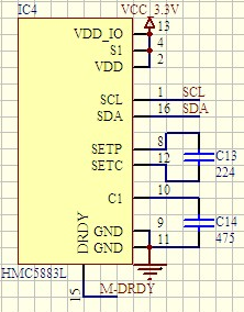
Among them, DRDY's explanation in the data manual is: data ready, interrupt pin. Internally pulled high. Optional connection. It was not used this time.
3.2 HMC5883 data reading and conversion
Like MPU6050, the data read from MPU is also of 16 bit integer type, and short type is required. The read data is the magnetic force of the magnetometer in x, y and z directions, which is recorded as mx, my and mz. In flight control, the magnetometer is used to measure the yaw angle, and the conversion formula is as follows:
yaw = atan2(my, mx) * (180 / 3.14159) + 180 (in °)Among them, the yaw is 0 ° to the north, increasing to the East until 360 ° after one circle.
3.3 HMC5883 procedure
Like MPU6050, the program consists of three parts, hmc5883.h, hmc5883.c, and main.c, as follows:
#ifndef __HMC5883_H
#define __HMC5883_H
#include "iic.h"

//============HMC5883 register address=========================
#define HMC5883_ADDR				0X1E<<1		// HMC address in IIC bus

#define HMC5883_CONFIG_REG_A		0x00		// Configuration register A
#define HMC5883_CONFIG_REG_B		0x01		// Configuration register B
#define HMC5883_MODE_REG			0x02		// Mode register
#define HMC5883_MAG_XOUTH_REG		0x03		// Data output X MSB register
#define HMC5883_MAG_XOUTL_REG		0x04		// Data output X LSB register
#define HMC5883_MAG_ZOUTH_REG		0x05		// Data output Z MSB register
#define HMC5883_MAG_ZOUTL_REG		0x06		// Data output Z LSB register
#define HMC5883_MAG_YOUTH_REG		0x07		// Data output Y MSB register
#define HMC5883_MAG_YOUTL_REG		0x08		// Data output Y LSB register
#define HMC5883_STA_REG				0x09		// Status register
#define HMC5883_IDEN_REG_A			0x10		// Identification register A
#define HMC5883_IDEN_REG_B			0x11		// Identification register B
#define HMC5883_IDEN_REG_C			0x12		// Identification register C

//====================User function=========================
#define HMC5883_MODE				0x00		// 0x00 continuous measurement mode, 0x01 single measurement mode (default)

void HMC5883_Init(void);
float HMC5883_GetAngle(void);

#endif
#include "iic.h"
#include "hmc5883.h"
#include <math.h>

/* Magnetometer 5883 initialization	*/
void HMC5883_Init(void)
{
	if (IIC_WriteAddrRegByte(HMC5883_ADDR, HMC5883_MODE_REG, HMC5883_MODE))
		printf("HMC5883 Init failed\r\n");
	else
		printf("HMC5883 Init Success\r\n");
}

/* Calculate the angle according to the magnetometer value						*/
/* Return value: angle								*/
/* 0 ° in the north direction, increasing to 360 ° in the east direction		*/
float HMC5883_GetAngle(void)
{
	uint8_t buf[6] ={0}, res;
	short mx, my, mz;							// Raw data read 16 bits
	float angle;

	res = IIC_ReadAddrRegBytes(HMC5883_ADDR, HMC5883_MAG_XOUTH_REG, 6, buf);

	if (res == 0)
	{
		mx = ((short)buf[0]<<8) | buf[1];		// To cast to the short type, short is 2 bytes, and the read buf[0],buf[1] is also 2 bytes. int is four bytes
		mz = ((short)buf[2]<<8) | buf[3];		// (int)65534=65534, (short)65534=-2
		my = ((short)buf[4]<<8) | buf[5];
	}

	angle = atan2((double)my, (double)mx) * (180.0/3.1415926) + 180;	// Get the angle according to the original data
	return angle;
}
#include "sys.h"
#include "delay.h"
#include "usart.h"
#include "led.h"
#include "FreeRTOS.h"
#include "task.h"
#include "hmc5883.h"
#include <math.h>

#define LED_TASK_PRIO 		1
#define LED_STK_SIZE		32
TaskHandle_t LED_TASK_Handler;

#define HMC5883_TASK_PRIO 	3
#define HMC5883_STK_SIZE	256
TaskHandle_t HMC5883_TASK_Handler;

void LED_Task(void *arg);			// LED task function
void HMC5883_Task(void *arg);		// HMC5883 task function

int main(void)
{
	HAL_Init();
	Stm32_Clock_Init(360, 25, 2, 8);	// 180M
	delay_init(180);
	uart_init(115200);

	IIC_Init();
	LED_Init();
	HMC5883_Init();

	taskENTER_CRITICAL();

	xTaskCreate((TaskFunction_t	) 			LED_Task,																// Create LED task
				(const char*	)			"LED_Task",
				(uint16_t		)			LED_STK_SIZE,
				(void*			)			NULL,
				(UBaseType_t	)			LED_TASK_PRIO,
				(TaskHandle_t*	)			&LED_TASK_Handler
				);
	xTaskCreate(HMC5883_Task, "HMC5883_Task", HMC5883_STK_SIZE, NULL, HMC5883_TASK_PRIO, &HMC5883_TASK_Handler);	// Create HMC5883 task
	taskEXIT_CRITICAL();
	vTaskStartScheduler();

	return 0;
}

/* Realize LED flashing, program running indicator	*/
void LED_Task(void *arg)
{
	while (1)
	{
		LED = 0;
		delay_ms(200);
		LED = 1;
		delay_ms(300);
	}
}

/* Achieve the angle between HMC5883 and the north, 0 ° in the north, increasing to 360 ° in the East*/
void HMC5883_Task(void *arg)
{
	float angle;
	while (1)
	{
		angle = HMC5883_GetAngle();
		printf("\r\nHMC5883 measurement result ===============================\r\n");
		printf("angle = %f°\r\n", angle);
		delay_ms(500);
	}
}
4, MS5611 principle and data reading
4.1 principle of ms5611
The 7-bit address of MS5611 is 0x77.
The schematic diagram of MS5611 is as follows:
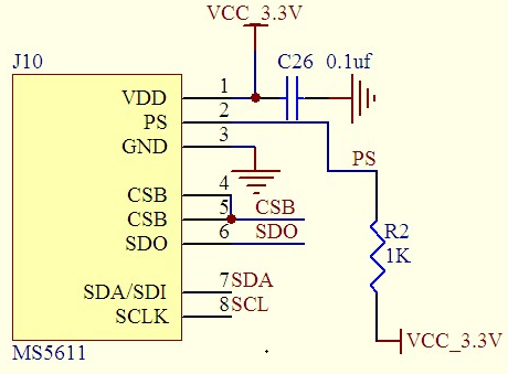
PS communication protocol selection, 1: IIC communication protocol, 0: SPI communication protocol
CSB chip selection, effective at low level
SDO serial data output, used for SPI communication, not used for IIC
4.2 MS5611 data conversion
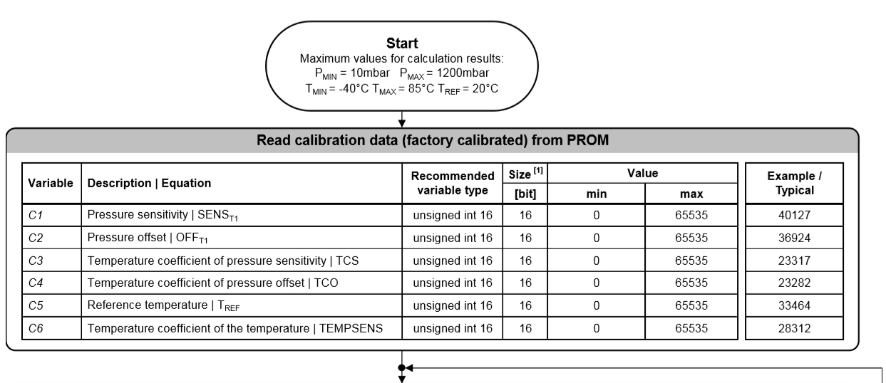
When reading the internal data of MS5611, first read six 16 digit numbers, which are some coefficients:
1. C[0] pressure sensitivity: SENS_T1
 2. C[1] pressure offset: OFF_T1
 3. Temperature coefficient of C [2] pressure sensitivity: TCS
 4. Temperature coefficient of C [3] pressure shift: TCO
 5. C[4] reference temperature: T_REF
 6. Temperature coefficient of C [5] temperature: TEMPSENS
The second is to read the digital values of air pressure and temperature, which are all 24 bits (3Bytes) data.
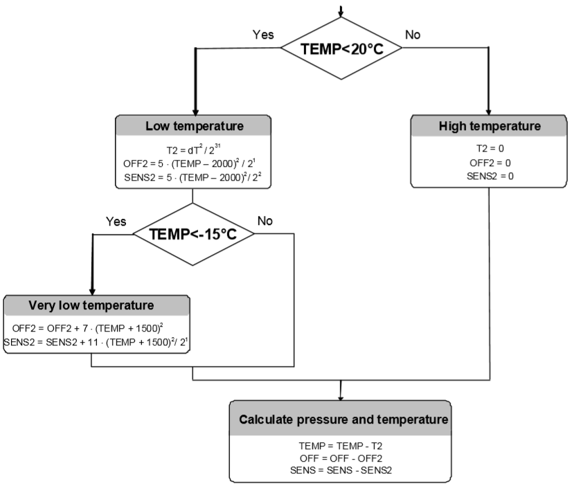
Finally, according to the algorithm of data manual, calculate the temperature and air pressure. The algorithm flow of data manual is as follows. The first and second diagrams are originally together, and give the temperature calculation method (expanded by 100 times, unit ° C). The air pressure calculation also needs to be iterated once through the third diagram, and then use the formula P = D1 * SENS - OFF. The barometer is in Pa.
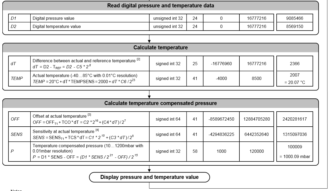
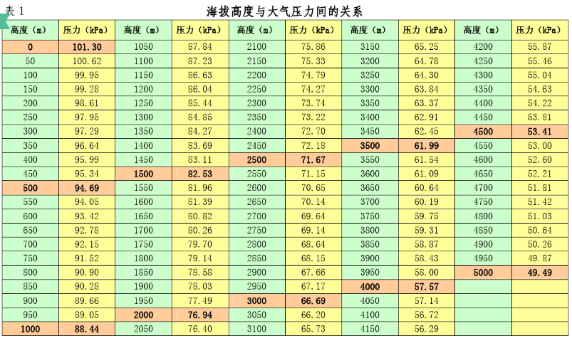
The temperature is increased by 100 times, so it is easy to judge whether it is normal. But how much normal pressure data is normal? High school chemistry said that a standard atmospheric pressure is the atmospheric pressure at sea level, 101.325kPa. High school physics also said that with the rise of altitude... Don't look at the specific relationship. Use a map to explain the problem. According to your altitude, you can preliminarily judge whether the data is right or not.
In order to better understand the process, you can check the algorithm in ms5611.c. The name of the variable in the above flow chart is used.
4.3 MS5611 procedure
There are still three files, ms5611.h, ms5611.c and main.c. There are a lot of comments in them, which will not be described in detail.
// ms5611.h defines MS5611 address and some operations

#ifndef _MS5611_H
#define _MS5611_H
#include "sys.h"

/*============ MS5611 Register address========================*/
#define MS5611_ADDR			0x77<<1	// MS5611 8-bit address

#define MS5611_RST			0x1E	// Reset command
#define MS5611_D1_OSR_256	0x40	// MS5611 air pressure (D1) over sampling rate 256
#define MS5611_D1_OSR_512	0x42
#define MS5611_D1_OSR_1024	0x44
#define MS5611_D1_OSR_2048	0x46
#define MS5611_D1_OSR_4096	0x48

#define MS5611_D2_OSR_256	0x50	// MS5611 temperature (D2) over sampling rate 256
#define MS5611_D2_OSR_512	0x52
#define MS5611_D2_OSR_1024	0x54
#define MS5611_D2_OSR_2048	0x56
#define MS5611_D2_OSR_4096	0x58

#define MS5611_ADC_RD		0x00	// ADC read command
#define MS5611_PROM_RD		0xA2	// PROM read command, manual from 0xa0, 0xa2,..., 0xae, 8 bits in total
#define MS5611_RROM_CRC		0xAE    // Actually, C1-C6 corresponds to 0xA2, 0xA4, 0xA6, 0xA8, 0xAA, 0xAC

/*=================== User defined management========================*/
#define MS5611_D1_OSR		MS5611_D1_OSR_256		// Air pressure (D1) oversampling 256
#define MS5611_D2_OSR		MS5611_D2_OSR_256		// Temperature (D2) oversampling 256

uint8_t MS5611_Init(void);							// MS5611 initialization
uint32_t MS5611_DoConv(uint8_t cmd);				// MS5611 get digital pressure and temperature
void MS5611_GetTemperaturePressure(float *temperature, float *pressure); // Get real pressure and temperature

#endif
There is also a proper term in the program - oversampling. Oversampling is to sample analog signals at a frequency much higher than twice the signal bandwidth. Oversampling can push the quantization noise to a higher frequency, so that the system can choose a lower-pass filter with a higher cut-off frequency, which makes the attenuation of the signal we are concerned about smaller. (the preceding sentence is just a passing check. It doesn't matter if you can't understand it.)
// ms5611.c is mainly based on MS5611 datasheet to realize the calculation of temperature and pressure

#include "ms5611.h"
#include "sys.h"
#include "delay.h"
#include "usart.h"
#include "iic.h"

/**************************************************************************/
// 					MS5611 get air pressure and temperature
// 					  Algorithm reference data book
/**************************************************************************/

/* Prom It stores six 16 bit data, meaning as follows:
   1. C[0] Pressure sensitivity: SENS_T1
   2. C[1] Pressure offset: OFF_T1
   3. C[2] Temperature coefficient of pressure sensitivity: TCS
   4. C[3] Temperature coefficient of pressure shift: TCO
   5. C[4] Reference temperature: T_REF
   6. C[5] Temperature coefficient of temperature: TEMPSENS
*/
static uint16_t C[6];

/* Initialize MS5611, including resetting and obtaining the value in Prom	*/
/* Return value 0 -- initialization succeeded						*/
/*		  1--initialization failed						*/
uint8_t MS5611_Init(void)
{
	u8 i;
	u8 d[2];
	IIC_Start();
	if (IIC_WriteByte(MS5611_ADDR))			// Address of transmitting device
	{
		printf("NOT find MS5611\r\n");
		return 1;
	}
	IIC_WriteByte(MS5611_RST);				// Send reset signal
	IIC_Stop();
	printf("MS5611 Init Success\r\n");
	delay_ms(100);

	for (i=0; i<6; i++)						// Read data in Prom
	{
		IIC_ReadAddrRegBytes(MS5611_ADDR, MS5611_PROM_RD + i*2, 2, d); // Read 6 numbers, 16 bits each, so + i*2
		C[i] = ((uint16_t)d[0] << 8) | d[1];
		delay_ms(5);
	}
	delay_ms(100);
	return 0;
}

/* MS5611 Conversion for obtaining digital value of temperature or air pressure		*/
/* cmd: MS5611_D1_OSR Obtain air pressure			*/
/*		MS5611_D2_OSR Obtain temperature			*/
uint32_t MS5611_DoConv(uint8_t cmd)
{
	uint32_t result = 0;
	uint8_t conv[3];
	IIC_Start();
	IIC_WriteByte(MS5611_ADDR);
	IIC_WriteByte(cmd);
	IIC_Stop();
	delay_ms(100);

	IIC_ReadAddrRegBytes(MS5611_ADDR, MS5611_ADC_RD, 3, conv);

	result = (uint32_t)conv[0] * 65535 + (uint32_t)conv[1] * 256 + (uint32_t)conv[2];
	return result;
}

/* MS5611 Conversion for obtaining true value of temperature or air pressure		*/
/* temperature -- Temperature (° C)				*/
/* pressure -- Air pressure (kPa)				*/
/* In order to keep consistent with the formula in the data manual, the variable name does not change	*/
void MS5611_GetTemperaturePressure(float *temperature, float *pressure)
{
	uint32_t D1, D2;												// D1--Pressure digital value, D2--Temperature digital value
	float dT, TEMP;
	double OFF, SENS;
	float P;
	float T2, OFF2, SENS2;

	D1 = MS5611_DoConv(MS5611_D1_OSR);								// Obtain the digital value of air pressure
	D2 = MS5611_DoConv(MS5611_D2_OSR);								// Get the numerical value of air temperature

	dT = D2 - (((uint32_t)C[4]) << 8); 								// dT = D2 - T_REF = D2 - C5 * 2^8
	TEMP = 2000.0 + ((float)dT / 8192.0) * ((float) C[5] / 1024.0);	// TEMP = 20°C + dT * TEMPSENS = 2000 + dT * C6 / 2^23
	OFF = ((int64_t)C[1]<<16) + ((double)C[3] * dT) / 128.0;		// OFF = OFF_T1 + TCO*dT = C1*2^15 + (C3*dT)/2^8
	SENS = ((int64_t)C[0]<<15) + ((double)C[2] * dT) / 256.0; 		// SENS = SENS_T1 + TCS*dT = C1*2^15 + (C3*dT)/2^8

	if (TEMP < 2000)												// Low temperature < 20 ° C
	{
		T2 = (float)((dT / 32768.0) * (dT / 65536.0));				// T2 = dT^2 / 2^31
		OFF2 = (float)(2.5 * (TEMP - 2000) * (TEMP - 2000));		// OFF2 = 5*(TEMP-2000)^2 / 2
		SENS2 = (float)(1.25 * (TEMP - 2000) * (TEMP - 2000)); 		// SENS2 = 5*(TEMP-2000)^2 / 4
		if (TEMP < -1500)											// Ultra low temperature < - 15 ° C
		{
			OFF2 += 7.0 * ((TEMP+1500) * (TEMP+1500));				// OFF2 = OFF2 + 7*(TEMP+1500)^2
			SENS2 += 5.5 * ((TEMP+1500) * (TEMP+1500));				// SENS2 = SENS2 + 11*(TEMP+1500)^2/2
		}
	}
	else															// high temperature
	{
		T2 = 0;
		OFF2 = 0;
		SENS2 = 0;
	}

	TEMP -= T2;														// TEMP = TEMP - T2
	OFF -= OFF2;													// OFF = OFF - OFF2
	SENS -= SENS2;													// SENS = SENS - SENS2

	P = (float)(((float)D1 / 32768.0) * (SENS / 2097152.0) - (OFF / 32768.0));// P = D1*SENS-OFF = (D1*SENS/2^21 - OFF) / 2^15

	*temperature = TEMP / 100.0;									// The temperature is increased by 100 times, divided by 100 here
	*pressure = P /1000.0;											// The air pressure is in kilopascals, divided by 1000 here
}
#include "sys.h"
#include "delay.h"
#include "usart.h"
#include "led.h"
#include "FreeRTOS.h"
#include "task.h"
#include "ms5611.h"
#include <math.h>

#define LED_TASK_PRIO 		1
#define LED_STK_SIZE		32
TaskHandle_t LED_TASK_Handler;

#define MS5611_TASK_PRIO 	4
#define MS5611_STK_SIZE		256
TaskHandle_t MS5611_TASK_Handler;

void LED_Task(void *arg);				// LED task function
void MS5611_Task(void *arg);			// MS5611 task function

int main(void)
{
	HAL_Init();
	Stm32_Clock_Init(360, 25, 2, 8);	// 180M
	delay_init(180);
	uart_init(115200);

	IIC_Init();
	LED_Init();
	MS5611_Init();

	taskENTER_CRITICAL();

	xTaskCreate((TaskFunction_t	) 			LED_Task,																// Create LED task
				(const char*	)			"LED_Task",
				(uint16_t		)			LED_STK_SIZE,
				(void*			)			NULL,
				(UBaseType_t	)			LED_TASK_PRIO,
				(TaskHandle_t*	)			&LED_TASK_Handler
				);
	xTaskCreate(MS5611_Task, "MS5611_Task", MS5611_STK_SIZE, NULL, MS5611_TASK_PRIO, &MS5611_TASK_Handler);			// Create MS5611 task
	taskEXIT_CRITICAL();
	vTaskStartScheduler();

	return 0;
}

/* Realize LED flashing, program running indicator	*/
void LED_Task(void *arg)
{
	while (1)
	{
		LED = 0;
		delay_ms(200);
		LED = 1;
		delay_ms(300);
	}
}

/* Realize MS5611 to obtain temperature and air pressure	*/
void MS5611_Task(void *arg)
{
	float temperature, pressure;
	while (1)
	{

		MS5611_GetTemperaturePressure(&temperature, &pressure);
		printf("\r\nMS5611 measurement result ===============================\r\n");
		printf("tempereture = %.2f°C\r\n", temperature);
		printf("pressure = %.3fkPa\r\n", pressure);
		delay_ms(500);
	}
}
5. Summary
The above is IIC communication protocol and 10DOF data reading. With these data, we can move on to the next step, data fusion.
If there is any problem in the program test, please leave a message in the comment area. If you really can't understand the program with the operating system, you can also leave a message.
The article inevitably appears the fallacy, please correct!
- end -