STM32 uses DHT11 and outputs the results to a seven-segment digital tube (proteus simulation)
Circuit diagram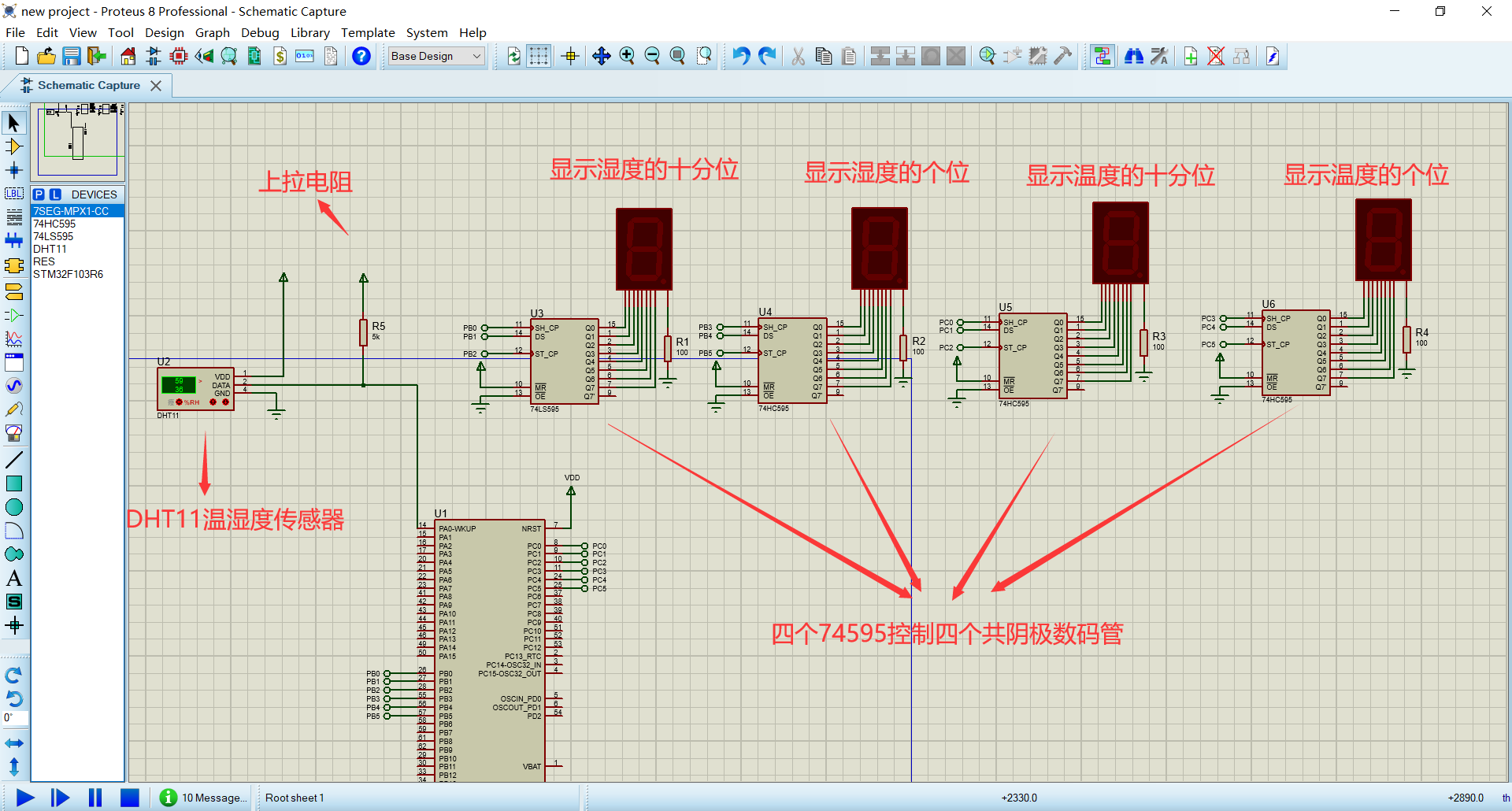
Step 1: Test environment after DHT11 is powered on (wait for 1S after DHT11 is powered on to get over the unstable state during which no instructions can be sent)
Temperature and humidity data, recording data, while the DATA cable of DHT11 is pulled up by the pull-up resistance and remains at a high level; at this time, DHT11's
The DATA pin is in the input state and detects external signals at all times.Step 2: The microprocessor I/O is set to output low level at the same time, and the low level retention time cannot be less than 18 Ms. Then the microprocessor I/O
Set to the input state, because of the pull-up resistance, the I/O of the microprocessor, that is, the DATA cable of DHT11, also increases, waiting for DHT11 to do
Out the answer signal and send the signal as shown in the figure: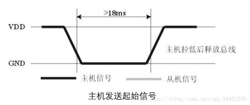
Step 3: The DATA pin of DHT11 detects that the external signal has a low level. Wait for the low level of the external signal to end. After delay, the DATA of DHT11
Pin is in output state, output low level of 80 microseconds as response signal, then output high level of 80 microseconds to notify peripheral ready to connect
Receive data, the microprocessor I/O is in the input state at this time, after I/O has been detected to have a low level (DHT11 response signal), wait 80 microseconds
After high level data reception, send signal as shown in the figure: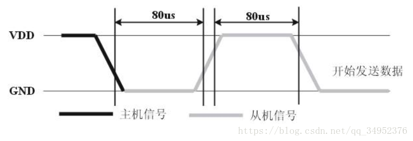
int main(void)
{


	//?????????

  /* USER CODE BEGIN 1 */

  /* USER CODE END 1 */

  /* MCU Configuration--------------------------------------------------------*/

  /* Reset of all peripherals, Initializes the Flash interface and the Systick. */
  HAL_Init();

  /* USER CODE BEGIN Init */

  /* USER CODE END Init */

  /* Configure the system clock */
  SystemClock_Config();

  /* USER CODE BEGIN SysInit */

  /* USER CODE END SysInit */

  /* Initialize all configured peripherals */
  MX_GPIO_Init();
  /* USER CODE BEGIN 2 */
	 GPIO_InitTypeDef GPIO_InitStruct = {0};
   //Port Initialization
		HAL_GPIO_WritePin(GPIOB, 1, 0);
		HAL_GPIO_WritePin(GPIOB, 4, 0);

		HAL_GPIO_WritePin(GPIOB, 8, 0);
		HAL_GPIO_WritePin(GPIOB, 32, 0);

	  HAL_GPIO_WritePin(GPIOA, 1, 1);
	  int num[10][8]={{0,0,1,1,1,1,1,1},{0,0,0,0,0,1,1,0},{0,1,0,1,1,0,1,1},
	               {0,1,0,0,1,1,1,1},{0,1,1,0,0,1,1,0},{0,1,1,0,1,1,0,1},
	               {0,1,1,1,1,1,0,1},{0,0,0,0,0,1,1,1},{0,1,1,1,1,1,1,1},{0,1,1,0,1,1,1,1}};
		//int data[8];
  /* Infinite loop */
  /* USER CODE BEGIN WHILE */
		int t[8];//Binary of temperature
		int h[8];//Binary Humidity
  while (1)
  {

		//Set pa port as output first
	GPIO_InitStruct.Pin = 1;
  GPIO_InitStruct.Mode = GPIO_MODE_OUTPUT_PP;
  GPIO_InitStruct.Pull = GPIO_NOPULL;
  GPIO_InitStruct.Speed = GPIO_SPEED_FREQ_LOW;
  HAL_GPIO_Init(GPIOA, &GPIO_InitStruct);
		//Start PA Port
	HAL_GPIO_WritePin(GPIOA, 1, 0);
	HAL_Delay(100);
	HAL_GPIO_WritePin(GPIOA, 1, 1);
		//Set pa port as input to read data
		GPIO_InitStruct.Pin = 1;
  GPIO_InitStruct.Mode = GPIO_MODE_INPUT;
  GPIO_InitStruct.Pull = GPIO_NOPULL;
  HAL_GPIO_Init(GPIOA, &GPIO_InitStruct);

		//Detect whether to start

		while(HAL_GPIO_ReadPin(GPIOA,1)==0);

		while(HAL_GPIO_ReadPin(GPIOA,1)==1);

		//Start receiving data after startup
	 int t[8];//Binary of temperature
	 int h[8];//Binary Humidity
	 int time=0;
   int flag=-1;
		for(int i=0;i<24;i++)
   {
		 while(HAL_GPIO_ReadPin(GPIOA, 1)==0);
     while(HAL_GPIO_ReadPin(GPIOA, 1)==1)
	  {
		 time++;
	  }
		if(i<8)
		{
			if(time>10)
			h[i]=1;
		  else
			h[i]=0;

		}
		else if(i>15)
		{
			flag++;
			if(time>10)
			t[flag]=1;
		  else
			t[flag]=0;

		}
		time=0;
 }
	 //Converting data
 int H=0;int T=0;
 int temp=1;

 //Finding humidity
 for(int i=0;i<8;i++)
 {
	 H+=temp*h[7-i];
	 temp*=2;
 }
 temp=1;
 //Calculating temperature
 for(int i=0;i<8;i++)
 {
	 T+=temp*t[7-i];
	 temp*=2;
 }


	//Separate digits from decimal digits
		int a=0,b=0,c=0,d=0;
		b=H%10;//Find out the humidity position
    a=H/10;//Humidity Ten
    d=T%10;//Temperature bits
    c=T/10;//Temperature tenths

  //Humidity display
		for(int i=0;i<8;i++)
 {
     HAL_GPIO_WritePin(GPIOB, 2, num[a%10][i]);
     HAL_GPIO_WritePin(GPIOB, 1, 1);
     HAL_GPIO_WritePin(GPIOB, 1, 0);
 }
    HAL_GPIO_WritePin(GPIOB, 4, 1);
    HAL_GPIO_WritePin(GPIOB, 4, 0);

  for(int i=0;i<8;i++)
 {
     HAL_GPIO_WritePin(GPIOB, 16, num[b%10][i]);
     HAL_GPIO_WritePin(GPIOB, 8, 1);
     HAL_GPIO_WritePin(GPIOB, 8, 0);
 }
    HAL_GPIO_WritePin(GPIOB, 32, 1);
    HAL_GPIO_WritePin(GPIOB, 32, 0);

 //Temperature display
 for(int i=0;i<8;i++)
 {
     HAL_GPIO_WritePin(GPIOC, 2, num[c%10][i]);
     HAL_GPIO_WritePin(GPIOC, 1, 1);
     HAL_GPIO_WritePin(GPIOC, 1, 0);
 }
    HAL_GPIO_WritePin(GPIOC, 4, 1);
    HAL_GPIO_WritePin(GPIOC, 4, 0);

  for(int i=0;i<8;i++)
 {
     HAL_GPIO_WritePin(GPIOC, 16, num[d%10][i]);
     HAL_GPIO_WritePin(GPIOC, 8, 1);
     HAL_GPIO_WritePin(GPIOC, 8, 0);
 }
    HAL_GPIO_WritePin(GPIOC, 32, 1);
    HAL_GPIO_WritePin(GPIOC, 32, 0);

  //------------------------------------
   GPIO_InitStruct.Pin = 1;
  GPIO_InitStruct.Mode = GPIO_MODE_OUTPUT_PP;
  GPIO_InitStruct.Pull = GPIO_NOPULL;
  GPIO_InitStruct.Speed = GPIO_SPEED_FREQ_LOW;
  HAL_GPIO_Init(GPIOA, &GPIO_InitStruct);


 HAL_GPIO_WritePin(GPIOA, 1, 1);

 HAL_Delay(500);
 }


  }