Article catalog
Summary
I saw it today Weidongshan upgraded full series embedded video bus device driver model After reading the video of this section, I feel a sense of incomprehension. Therefore, I analyze the corresponding source code of the video of this section, and the results are as follows:
Functional diagram
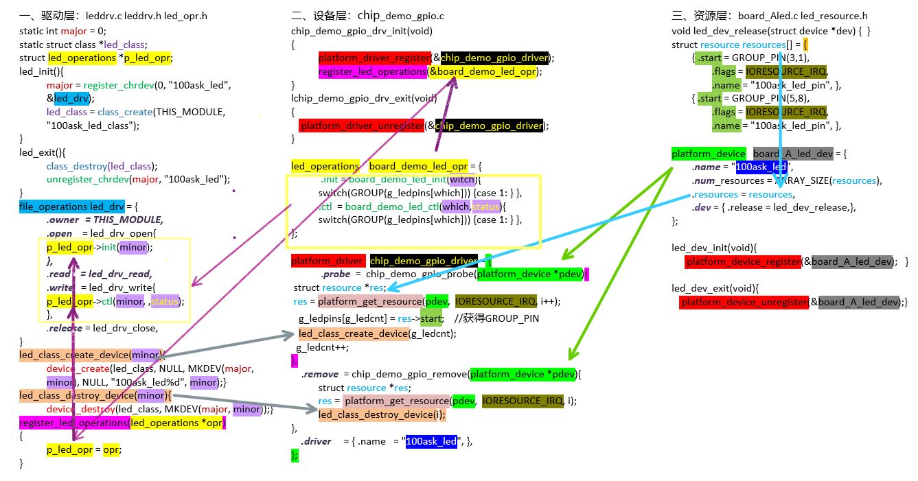
model analysis
The model has three layers:
1, Driving layer
2, Equipment layer
3, Resource layer
The data flow direction is roughly resource layer - > device layer - > driver layer
Resource layer - > device layer
The number of pins and devices to be used are defined in the resource array of the resource layer:
struct resource {
	resource_size_t start;
	resource_size_t end;
	const char *name;
	unsigned long flags;
	struct resource *parent, *sibling, *child;
};
Example:
static struct resource resources[] = {
        {
                .start = GROUP_PIN(3,1),
                .flags = IORESOURCE_IRQ,
                .name = "100ask_led_pin",
        },
        {
                .start = GROUP_PIN(5,8),
                .flags = IORESOURCE_IRQ,
                .name = "100ask_led_pin",
        },
};
In the device layer chip demo GPIO. C, the data in the resource is passed to the device layer through the platform get resource() function, and the device is created in the. Probe = chip demo GPIO probe function, and the device is unloaded in the. Remove = chip demo GPIO remove function
static struct platform_driver chip_demo_gpio_driver = {
    .probe      = chip_demo_gpio_probe,
    .remove     = chip_demo_gpio_remove,
    .driver     = {
        .name   = "100ask_led",
    },
};

static int chip_demo_gpio_probe(struct platform_device *pdev)
{
    struct resource *res;
    int i = 0;

    while (1)
    {
        res = platform_get_resource(pdev, IORESOURCE_IRQ, i++);
        if (!res)
            break;

        g_ledpins[g_ledcnt] = res->start;
        led_class_create_device(g_ledcnt);
        g_ledcnt++;
    }
    return 0;

}

static int chip_demo_gpio_remove(struct platform_device *pdev)
{
    struct resource *res;
    int i = 0;

    while (1)
    {
        res = platform_get_resource(pdev, IORESOURCE_IRQ, i);
        if (!res)
            break;

        led_class_destroy_device(i);
        i++;
        g_ledcnt--;
    }
    return 0;
}
Device layer - > driver layer
The function to create a device is defined in the driver layer, leddrv.c: LED class create device(); LED class destroy device() is defined in the driver layer, leddrv.c:
static struct class *led_class;

void led_class_create_device(int minor)
{
	device_create(led_class, NULL, MKDEV(major, minor), NULL, "100ask_led%d", minor); /* /dev/100ask_led0,1,... */
}
void led_class_destroy_device(int minor)
{
	device_destroy(led_class, MKDEV(major, minor));
}
The device layer sets the hardware in the board demo led OPR structure, and uses the register led operation & board demo led OPR function in the chip demo GPIO DRV init() to transfer the contents of the LED operations board demo led OPR structure in the device layer to the driver layer.
Led operations board demo led OPR structure content:
/* There is no hardware operation in the routine, only a framework is written */
static struct led_operations board_demo_led_opr = {
    .init = board_demo_led_init,	//In this function, enable clock, set pin working mode, and set I / O mode
    .ctl  = board_demo_led_ctl,		//Set pin level in this function
};

static int board_demo_led_init (int which) /* Initialization LED, which - which LED */
{
    //printk("%s %s line %d, led %d\n", __FILE__, __FUNCTION__, __LINE__, which);

    printk("init gpio: group %d, pin %d\n", GROUP(g_ledpins[which]), PIN(g_ledpins[which]));
    switch(GROUP(g_ledpins[which]))
    {
        case 0:
        {
            printk("init pin of group 0 ...\n");
            break;
        }
        case 1:
        {
            printk("init pin of group 1 ...\n");
            break;
        }
        case 2:
        {
            printk("init pin of group 2 ...\n");
            break;
        }
        case 3:
        {
            printk("init pin of group 3 ...\n");
            break;
        }
    }

    return 0;
}

static int board_demo_led_ctl (int which, char status) /* Control LED, which LED, status:1-on, 0-off */
{
    //printk("%s %s line %d, led %d, %s\n", __FILE__, __FUNCTION__, __LINE__, which, status ? "on" : "off");
    printk("set led %s: group %d, pin %d\n", status ? "on" : "off", GROUP(g_ledpins[which]), PIN(g_ledpins[which]));

    switch(GROUP(g_ledpins[which]))
    {
        case 0:
        {
            printk("set pin of group 0 ...\n");
            break;
        }
        case 1:
        {
            printk("set pin of group 1 ...\n");
            break;
        }
        case 2:
        {
            printk("set pin of group 2 ...\n");
            break;
        }
        case 3:
        {
            printk("set pin of group 3 ...\n");
            break;
        }
    }

    return 0;
}
Chip? Demo? GPIO? DRV? Init() function:
static int __init chip_demo_gpio_drv_init(void)
{
    int err;

    err = platform_driver_register(&chip_demo_gpio_driver);

    /* This function is defined in the driver layer, leddrv.c, where it is used to transfer the contents of board, demo, led and OPR into the driver layer's P, led and OPR */
    register_led_operations(&board_demo_led_opr);

    return 0;
}
The definition of register? Led? Error () in device layer leddrv.c
struct led_operations *p_led_opr;
void register_led_operations(struct led_operations *opr)
{
	p_led_opr = opr;
}
Then the hardware is operated in the open and write functions through P led OPR - > init() and P led OPR - > ctl()
/* 2. Define your own file operations structure                                              */
static struct file_operations led_drv = {
	.owner	 = THIS_MODULE,
	.open    = led_drv_open,
	.read    = led_drv_read,
	.write   = led_drv_write,
	.release = led_drv_close,
};

/* 3. Implement the corresponding functions such as open/read/write, and fill in the file operations structure                   */
/* write(fd, &val, 1); */
static ssize_t led_drv_write (struct file *file, const char __user *buf, size_t size, loff_t *offset)
{
	int err;
	char status;
	struct inode *inode = file_inode(file);
	int minor = iminor(inode);

	printk("%s %s line %d\n", __FILE__, __FUNCTION__, __LINE__);
	err = copy_from_user(&status, buf, 1);

	/* Control LED according to secondary device number and status */
	p_led_opr->ctl(minor, status);

	return 1;
}

static int led_drv_open (struct inode *node, struct file *file)
{
	int minor = iminor(node);

	printk("%s %s line %d\n", __FILE__, __FUNCTION__, __LINE__);
	/* Initialize LED according to secondary device number */
	p_led_opr->init(minor);

	return 0;
}
summary
The summary is messy, but at present I only understand this step. If there is a new idea in the future, please change it. Thank you for watching.