Keywords: CubeMX, CubeIDE, STM32G031C8T6, AHT10, DRF1609H
Zigbee module (DRF1609H) is used in this project as wireless data transmission. Initialization of DRF1609H mainly involves the following aspects:
1. Set the type of node, which can be set as Router and End Device. Zigbee network has three types of nodes: Coordinator, Router, End Device. The Coordinator is connected to the computer to collect data. Here we are the collection node, so we only set it as Router or End Device.
2. Check whether the node has joined the network
3. If the node does not join the network, start automatic scanning to join the network
1. Setting of node type:
First, read the parameters of DRF1609H: G031 sends the parameter reading instruction to DRF1609H. After sending the parameters, there is a 500MS timeout waiting for the parameter reply. The parameter reply is 53 bytes in total, which is put in receiveConfigData.
	//--Read DRF1609H Configures --
	drf1609h_readModule();
	HAL_UART_Receive( &huart1, receivedConfigData, 53, 500 );
//------------------------------
void  drf1609h_readModule(void)
{
	drf1609h_sendedIns = sendIns_read;
	HAL_UART_Transmit_DMA( &huart1, readIns, 9 );
}
After reading the parameters, put the read parameters into the drf1609 structure after sorting out: it will be very convenient to use later. It is recommended that users do not change this part of the code, just copy it directly.
	//---If DRF1609H Error or Read Error ------
	while( readParameterProcess(receivedConfigData, 53) == 0 )
	{
		drf1609h_readModule();
		HAL_UART_Receive( &huart1, receivedConfigData, 53, 500 );
	}
//------------------------------
uint8_t  readParameterProcess(uint8_t  *inputData,  uint16_t  inputLen)
{
	uint8_t  result=0;

	uint8_t  tempXY=0;
	uint8_t  tempRight=0;
	uint8_t  i=0;

	tempXY = getXY(inputData, inputLen);

	if(inputData[0]==0xFA) { tempRight++; }
	if(inputData[1]==0x31) { tempRight++; }
	if(inputData[2]==0x0A) { tempRight++; }
	if(inputData[inputLen-1]==tempXY) { tempRight++; }

	if(tempRight==4)
	{
		//------
		drf1609.pointType = inputData[readHeaderLen +0];
		drf1609.PAN_ID = inputData[readHeaderLen +1]*256 + inputData[readHeaderLen +2];
		drf1609.Channel = inputData[readHeaderLen +3];
		drf1609.transferModel = inputData[readHeaderLen +4];
		drf1609.userAddress = inputData[readHeaderLen +5]*256 + inputData[readHeaderLen +6];
		drf1609.X7X8 = inputData[readHeaderLen +7]*256 + inputData[readHeaderLen +8];
		drf1609.uartBraudRate = inputData[readHeaderLen +9];
		drf1609.uartDataBits = inputData[readHeaderLen +10];
		drf1609.uartStopBits = inputData[readHeaderLen +11];
		drf1609.uartParity = inputData[readHeaderLen +12];
		drf1609.X13X14 = inputData[readHeaderLen +13]*256 + inputData[readHeaderLen +14];
		drf1609.antennaSelect = inputData[readHeaderLen +15];

		//-------
		for(i=0; i<8; i++)
		{
			drf1609.macAddress[i] = inputData[readHeaderLen +16 +i];
		}

		//--------
		drf1609.prePointType = inputData[readHeaderLen +24];
		drf1609.prePAN_ID = inputData[readHeaderLen +25]*256 + inputData[readHeaderLen +26];
		drf1609.preChannel = inputData[readHeaderLen +27];
		drf1609.preTransferModel = inputData[readHeaderLen +28];
		drf1609.preUserAddress = inputData[readHeaderLen +29]*256 + inputData[readHeaderLen +30];
		drf1609.X31X32 = inputData[readHeaderLen +31]*256 + inputData[readHeaderLen +32];
		drf1609.preUartBraudRate = inputData[readHeaderLen +33];
		drf1609.preUartDataBits = inputData[readHeaderLen +34];
		drf1609.preUartStopBits = inputData[readHeaderLen +35];
		drf1609.preUartParity = inputData[readHeaderLen +36];
		drf1609.X37X38 = inputData[readHeaderLen +37]*256 + inputData[readHeaderLen +38];
		drf1609.preAntennaSelect = inputData[readHeaderLen +39];

		//-----------
		drf1609.shortAddress = inputData[readHeaderLen +40]*256 + inputData[readHeaderLen +41];
		drf1609.X42 = inputData[readHeaderLen +42];
		drf1609.isSecurity = inputData[readHeaderLen +43];

		for(i=0; i<4; i++)
		{
			drf1609.securityCode[i] = inputData[readHeaderLen +44 +i];
		}

		result =1;
	}

	return result;
}
Then compare the read node type with the node type to be set. If not, write the node type to be set again:
if( drf1609H_setPontType != drf1609H_readPointType )
Process of writing:
1. Generate write parameters
2, write
3. Receive the parameters of the reply to see if the writing is correct
		getWriteIns(drf1609);

		drf1609h_writeModule();
		HAL_UART_Receive( &huart1, receivedConfigData, 5, 500 );
After the write is correct, restart the module (Note: the write parameters of DRF1609H take effect, and restart is required). Here, an IO port is used to control the RESET pin of DRF1609H to pull down and restart.
if( is_InsBack(receivedConfigData, 5) )
		{
			if(receivedConfigData[2] == 0x0A)
			{
				drf1609h_reset();
				HAL_Delay(2000);
				drf1609h_status = drf1609h_powerOn;
			}
			else
			{
				errorStart=1;
			}
		}
		else
		{
			errorStart=1;
		}
It should be noted that getWriteIns(drf1609) is a function that directly transforms the drf1609 structure into a write instruction. It is recommended that users do not modify this part and copy it directly for use
//---------------------------------------------------
void  getWriteIns(_zigbeeParameters  inputParameter)
{
	uint8_t   i=0;
	uint8_t  tempXY=0;

	writeIns[0]= 0xFC;
	writeIns[1]= 0x27;
	writeIns[2]= 0x07;

	writeIns[writeHeaderLen +0]= inputParameter.pointType;
	writeIns[writeHeaderLen +1]= (inputParameter.PAN_ID & 0xFF00)>>8;
	writeIns[writeHeaderLen +2]= inputParameter.PAN_ID & 0x00FF;
	writeIns[writeHeaderLen +3]= inputParameter.Channel;
	writeIns[writeHeaderLen +4]= inputParameter.transferModel;
	writeIns[writeHeaderLen +5]= (inputParameter.userAddress & 0xFF00)>>8;
	writeIns[writeHeaderLen +6]= inputParameter.userAddress & 0x00FF;
	writeIns[writeHeaderLen +7]= (inputParameter.X7X8 & 0xFF00)>>8;
	writeIns[writeHeaderLen +8]= inputParameter.X7X8 & 0x00FF;
	writeIns[writeHeaderLen +9]= inputParameter.uartBraudRate;
	writeIns[writeHeaderLen +10]= inputParameter.uartDataBits;
	writeIns[writeHeaderLen +11]= inputParameter.uartStopBits;
	writeIns[writeHeaderLen +12]= inputParameter.uartParity;
	writeIns[writeHeaderLen +13]= (inputParameter.X13X14 & 0xFF00)>>8;
	writeIns[writeHeaderLen +14]= inputParameter.X13X14 & 0x00FF;
	writeIns[writeHeaderLen +15]= inputParameter.antennaSelect;

	writeIns[writeHeaderLen +16]= inputParameter.prePointType;
	writeIns[writeHeaderLen +17]= (inputParameter.prePAN_ID & 0xFF00)>>8;
	writeIns[writeHeaderLen +18]= inputParameter.prePAN_ID & 0x00FF;
	writeIns[writeHeaderLen +19]= inputParameter.preChannel;
	writeIns[writeHeaderLen +20]= inputParameter.preTransferModel;
	writeIns[writeHeaderLen +21]= (inputParameter.preUserAddress & 0xFF00)>>8;
	writeIns[writeHeaderLen +22]= inputParameter.preUserAddress & 0x00FF;
	writeIns[writeHeaderLen +23]= (inputParameter.X31X32 & 0xFF00)>>8;  //--AS ReadParameter's X31 X32
	writeIns[writeHeaderLen +24]= inputParameter.X31X32 & 0x00FF;       //--AS ReadParameter's X31 X32
	writeIns[writeHeaderLen +25]= inputParameter.preUartBraudRate;
	writeIns[writeHeaderLen +26]= inputParameter.preUartDataBits;
	writeIns[writeHeaderLen +27]= inputParameter.preUartStopBits;
	writeIns[writeHeaderLen +28]= inputParameter.preUartParity;
	writeIns[writeHeaderLen +29]= (inputParameter.X37X38 & 0xFF00)>>8;  //--AS ReadParameter's X37 X38
	writeIns[writeHeaderLen +30]= inputParameter.X37X38 & 0x00FF;       //--AS ReadParameter's X37 X38
	writeIns[writeHeaderLen +31]= inputParameter.preAntennaSelect;
	writeIns[writeHeaderLen +32]= 0x1;
	writeIns[writeHeaderLen +33]= inputParameter.isSecurity;

	for(i=0; i<4; i++)
	{
		writeIns[writeHeaderLen +34 +i]= inputParameter.securityCode[i];
	}

	tempXY = getXY(writeIns, writeInsLen);

	writeIns[writeInsLen-1]= tempXY;
}
2. Check whether the node joins the network
Check whether the node joins the network. Here we use the command to read the signal strength of DRF1609H node. If the signal strength is read successfully (the returned data is correct), it indicates that DRF1609H has joined the network and the communication with Coordinator is normal.
This function is used to check whether the DRF1609H is connected to the network. If it is connected, reply 1. If not, reply 0
Note: This is 10 times of detection. If the Coordinator is not powered on and the node is detected all the time, it is not good for power consumption. The user should modify and use it according to the actual situation.
uint8_t drf1609h_isJoinedNet()
//----------------------
uint8_t  drf1609h_isJoinedNet()
{
	uint8_t   result=0;
	uint8_t   i=0;

	//MX_USART1_UART_Init();
	//HAL_Delay(10);
	for(i=0; i<8; i++)
	{
		receivedSignalData[i]=0;
	}

	drf1609h_requestSignalIndex();
	HAL_UART_Receive( &huart1, receivedSignalData, 8, 500 );
	HAL_Delay(1000);

	if( checkSignalData(receivedSignalData, 8) )
	{
		result=1;
		receivedSignalData[8] = drf1609.pointType;
		HAL_UART_Transmit_DMA( &huart1, receivedSignalData, 9 );
	}
	else
	{
		haveTryToJoinTimers++;
		if(haveTryToJoinTimers >= maxJoinTimers)
		{
			result=1;
		}
		else
		{
			result=0;
		}
	}


	return   result;
}
Detection process:
1. Send read signal strength command
2. Waiting for receiving reply data
3. If the received reply data is successful (has joined the network), the received data plus its own node type will be sent to the Coordinator to inform the node that it has joined successfully
	drf1609h_requestSignalIndex();
	HAL_UART_Receive( &huart1, receivedSignalData, 8, 500 );
	HAL_Delay(1000);

	if( checkSignalData(receivedSignalData, 8) )
	{
		result=1;
		receivedSignalData[8] = drf1609.pointType;
		HAL_UART_Transmit_DMA( &huart1, receivedSignalData, 9 );
	}
3. Start the node to join the network automatically
If you press the Function button of DRF1609H for three times, it will start to scan automatically. If you scan to the Coordinator, you can automatically join the network, and get "preset parameters for Router" from the Coordinator. Therefore, the node is not set, and the serial port of DRF1609H is not left on the board of our node, but by pressing the button for three times, it will automatically join the network and take out automatically Get the parameters.
1. Check whether DRF1609H is connected to the network, and use the command to read the signal strength
2. If you do not join the network, start to join the network automatically
3. After starting, wait for 12 seconds, and then read the signal strength to determine whether the network is joined
Note that there is a key on the board. If it is in low power consumption mode, it is recommended not to start this function. Use the key to join the network manually. If the Coordinator does not turn on, it will consume the battery quickly if it scans the network all the time.
	//-- Do 5 timers get Signal Index ----//
	for(i=0; i<5; i++)
	{
		drf1609h_requestSignalIndex();
		HAL_UART_Receive( &huart1, receivedSignalData, 8, 500 );
		HAL_Delay(500);

		if( checkSignalData(receivedSignalData, 8) )
		{
			tempVal++;
			i=5;
		}
		else
		{
			notGetSignalVal++;
		}
	}
    	drf1609h_autoJoinNet_Start();
    	HAL_Delay(12000);
Look at the code that automatically joins the network. In fact, it is to simulate three times of buttons:
After the start, two lights on DRF1609H will flash quickly. It is observed that one light is off and the other light flashes slowly, indicating that the DRF1609H has joined the network.
//---------------------------------------
/*   This Simulate Function Key to start
 *   point auto join net
 *   ____    ______    ______    ______
 *       |__|      |__|      |__|
 *
 *       120  200  120  200  120  200
 *
 *   ----------------------------------*/
void  drf1609h_autoJoinNet_Start()
{
	uint8_t  i=0;

	set_autoJoinNetPin_output();
	set_autoJoinNetPin_out_1();
	HAL_Delay(100);

	for(i=0; i<3; i++)
	{
		set_autoJoinNetPin_out_0();
		HAL_Delay(120);

		set_autoJoinNetPin_out_1();
		HAL_Delay(200);
	}

	set_autoJoinNetPin_input();
}
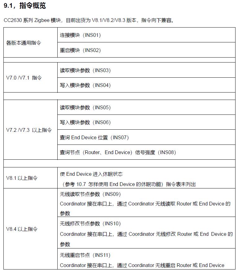
4. Relevant instructions of DRF1609H
There are instructions for reading parameters, reading signal strength, writing parameters, etc., which are listed in the project
If other functions need to be added, please refer to DRF1609H's manual
uint8_t    linkIns[9] = {0xFC, 0x06, 0x04, 0x44, 0x54, 0x4B, 0x52, 0x46, 0x81};      //---INS01
uint8_t    restartIns[9] = {0xFC, 0x06, 0x06, 0x44, 0x54, 0x4B, 0xAA, 0xBB, 0x50};   //---INS02
uint8_t    readIns[9] = {0xFC, 0x06, 0x0E, 0x44, 0x54, 0x4B, 0x52, 0x46, 0x8B};      //---INS05
uint8_t    writeIns[42];   //--INS06
uint8_t    requestSignalIns[9] = {0xFC, 0x06, 0x0C, 0x44, 0x54, 0x4B, 0x52, 0x46, 0x89};    //--INS08