Continue with the previous article
Actually, the last one is just some basic thing. This one tells you how to make your car follow the trail.
Fourth, how to adjust the speed of the motor (adjust the speed of the car) through pwm
1. Why can pwm speed up?
My understanding is that for DC motor, the first high level motor will rotate, if you change the proportion of high level occupancy, that is, let the motor receive less high level time in a unit time, its speed will be reduced.
Note that the pwm here is output by single-chip computer to the IN1-IN4 end driven by the motor, so we have to set up the software to output the desired high level, here is the main thing about the software.
2. How to connect stm32 and motor driver?
STM32 does not have a separate PWM module. It uses timers to output pwm. Each timer has four channels. We need to find the pins connected by the four channels of the timer, and then connect the four pins to the motor-driven input.First, briefly review the relevant knowledge of STM32 timer.First I checked the technical manual of the stm3210x series
You can see that we have three universal timers in this STM32F103C8T6 (all three timers have been used up in my project). Down, each timer has four channels, and we need to find the pins for each of these four channels.For example, the timer I used for the motor is TIM3. Looking at the definition of pin in the data manual, I find the following: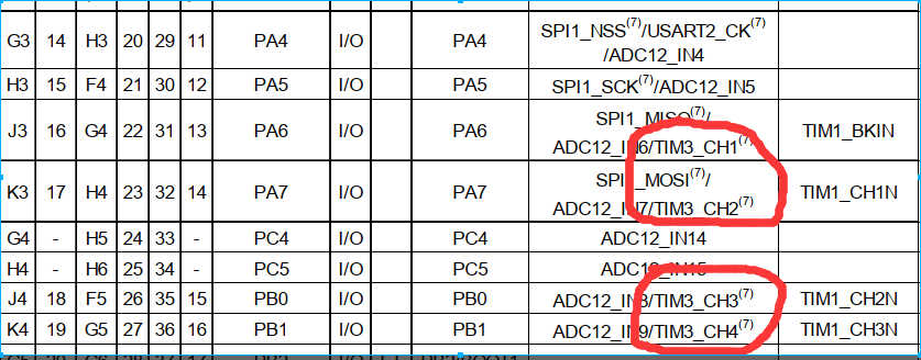
So the channel 1-4 of timer 3 corresponds to PA6,PA7,PB0,PB1 respectively. I connect these four pins to the motor-driven IN1-IN4 respectively, so we have set up the hardware circuit of the motor speed control.
3. How to set the timer output 4 adjustable pwm?
This is the most critical point. First, paste the code of my motor setup. Here is the moter.c program
#include "moter.h"

void CarGo(void)
{
  TIM_SetCompare1(TIM3 , 400);  //The larger the number, the slower the speed
  TIM_SetCompare2(TIM3 , 900);
  TIM_SetCompare3(TIM3 , 400);
  TIM_SetCompare4(TIM3 , 900);
}

void CarStop(void)
{
  TIM_SetCompare1(TIM3 , 900);
  TIM_SetCompare2(TIM3 , 900);
  TIM_SetCompare3(TIM3 , 900);
  TIM_SetCompare4(TIM3 , 900);
}

void CarBack(void)
{
  TIM_SetCompare1(TIM3 , 900);
  TIM_SetCompare2(TIM3 , 300);
  TIM_SetCompare3(TIM3 , 900);
  TIM_SetCompare4(TIM3 , 300);
}

void CarLeft(void)
{
  TIM_SetCompare1(TIM3 , 900);
  TIM_SetCompare2(TIM3 , 300);
  TIM_SetCompare3(TIM3 , 300);
  TIM_SetCompare4(TIM3 , 900);
}

void CarBigLeft(void)
{
  TIM_SetCompare1(TIM3 , 900);
  TIM_SetCompare2(TIM3 , 100);
  TIM_SetCompare3(TIM3 , 100);
  TIM_SetCompare4(TIM3 , 900);
}

void CarRight(void)
{
  TIM_SetCompare1(TIM3 , 300);
  TIM_SetCompare2(TIM3 , 900);
  TIM_SetCompare3(TIM3 , 900);
  TIM_SetCompare4(TIM3 , 300);

}

void CarBigRight(void)
{
  TIM_SetCompare1(TIM3 , 100);
  TIM_SetCompare2(TIM3 , 900);
  TIM_SetCompare3(TIM3 , 900);
  TIM_SetCompare4(TIM3 , 100);

}


void TIM3_PWM_Init(void)  //pwm settings and corresponding pin settings for TIM3
{
  GPIO_InitTypeDef GPIO_InitStructure;

  TIM_TimeBaseInitTypeDef TIM_TimeBaseStructure;
  TIM_OCInitTypeDef TIM_OCInitStructure;
  RCC_APB1PeriphClockCmd(RCC_APB1Periph_TIM3 , ENABLE);
  RCC_APB2PeriphClockCmd(RCC_APB2Periph_GPIOA | RCC_APB2Periph_GPIOB | RCC_APB2Periph_AFIO, ENABLE);


  TIM_TimeBaseStructure.TIM_Period = 899;
  TIM_TimeBaseStructure.TIM_Prescaler = 0;
  TIM_TimeBaseStructure.TIM_CounterMode = TIM_CounterMode_Up;
  TIM_TimeBaseStructure.TIM_ClockDivision = 0;
  TIM_TimeBaseInit(TIM3 , &TIM_TimeBaseStructure);

  //Port Reuse
  GPIO_InitStructure.GPIO_Pin = GPIO_Pin_6 | GPIO_Pin_7;   //Initialize A6/A7 ports to use
  GPIO_InitStructure.GPIO_Speed = GPIO_Speed_50MHz;
  GPIO_InitStructure.GPIO_Mode = GPIO_Mode_AF_PP;
  GPIO_Init(GPIOA, &GPIO_InitStructure);

  GPIO_InitStructure.GPIO_Pin = GPIO_Pin_0 | GPIO_Pin_1;   //Initialize B0/B1 port to use
  GPIO_InitStructure.GPIO_Speed = GPIO_Speed_50MHz;
  GPIO_InitStructure.GPIO_Mode = GPIO_Mode_AF_PP;
  GPIO_Init(GPIOB, &GPIO_InitStructure);

  //PWM Channel 1
  TIM_OCInitStructure.TIM_OCMode = TIM_OCMode_PWM2;
  TIM_OCInitStructure.TIM_OutputState = TIM_OutputState_Enable;
  TIM_OCInitStructure.TIM_OCPolarity = TIM_OCPolarity_High;
  TIM_OCInitStructure.TIM_Pulse = 900;
  TIM_OC1Init(TIM3 , &TIM_OCInitStructure);
  TIM_OC1PreloadConfig(TIM3 , TIM_OCPreload_Enable);

  //PWM Channel 2
  TIM_OCInitStructure.TIM_OCMode = TIM_OCMode_PWM2;
  TIM_OCInitStructure.TIM_OutputState = TIM_OutputState_Enable;
  TIM_OCInitStructure.TIM_OCPolarity = TIM_OCPolarity_High;
  TIM_OCInitStructure.TIM_Pulse = 900;
  TIM_OC2Init(TIM3 , &TIM_OCInitStructure);
  TIM_OC2PreloadConfig(TIM3 , TIM_OCPreload_Enable);

  //PWM Channel 3
  TIM_OCInitStructure.TIM_OCMode = TIM_OCMode_PWM2;
  TIM_OCInitStructure.TIM_OutputState = TIM_OutputState_Enable;
  TIM_OCInitStructure.TIM_OCPolarity = TIM_OCPolarity_High;
  TIM_OCInitStructure.TIM_Pulse = 900;
  TIM_OC3Init(TIM3 , &TIM_OCInitStructure);
  TIM_OC3PreloadConfig(TIM3 , TIM_OCPreload_Enable);

  //PWM Channel 4
  TIM_OCInitStructure.TIM_OCMode = TIM_OCMode_PWM2;
  TIM_OCInitStructure.TIM_OutputState = TIM_OutputState_Enable;
  TIM_OCInitStructure.TIM_OCPolarity = TIM_OCPolarity_High;
  TIM_OCInitStructure.TIM_Pulse = 900;
  TIM_OC4Init(TIM3 , &TIM_OCInitStructure);
  TIM_OC4PreloadConfig(TIM3 , TIM_OCPreload_Enable);

  TIM_Cmd(TIM3 , ENABLE);
}
The following is the contents of the moter.h file
#ifndef __MOTER_H
#define	__MOTER_H


#include "stm32f10x.h"


void TIM3_PWM_Init(void);
void CarGo(void);
void CarStop(void);
void CarBack(void);
void CarLeft(void);
void CarBigLeft(void);  //Turn Great Right
void CarRight(void);
void CarBigRight(void);   //Turn left

#endif
These codes are also very useful, calling TIM3_PWM_Init() before the main function completes the pin and timer initialization, then using the forward and backward turn functions directly afterwards.
Here are some key parameters of this function:
	TIM_TimeBaseStructure.TIM_Period = 899;
	TIM_TimeBaseStructure.TIM_Prescaler = 0;

	According to the periodic formula of the timer: Period=(arr+1)*(psc+1)/CLK=900/72000000,
	So set the timer reference frequency to 80KHZ
Looking at the settings of each pwm port, the main parameters are as follows:
	TIM_OCInitStructure.TIM_OCMode = TIM_OCMode_PWM2;
	TIM_OCInitStructure.TIM_OCPolarity = TIM_OCPolarity_High;
	TIM_OCInitStructure.TIM_Pulse = 900;//Pulse Width Settings
1. What does TIM_OCMode_PWM2 mean?
When the timer value is less than the comparator setting, the TIMX output foot outputs a valid low potential.
The TIMX output foot outputs a high potential when the timer value is greater than or equal to the comparator setting.
2, TIM_OCPolarity_High indicates that the starting wave is high potential
3, TIM_Pulse = 900 indicates a total pulse width of 900
Since the value of the counter is 899+1, the duty cycle is 1 at this time. We set the duty cycle by setting the comparison value again with the SetCompare function below.
4. Finally, we use the TIM_SetCompare1 (TIM3, 400) function to set the comparison value
For example, if we set the comparison value to 400, the total pulse width to 900, the initial potential to be high, and the PWM2 mode is set, then it will be low in 0-400 and high in 400-900.That is, the larger the value set for comparison, the shorter the time occupied by the high level.
For example, my forward function:
void CarGo(void)
{
  TIM_SetCompare1(TIM3 , 400);  //The larger the number, the slower the speed
  TIM_SetCompare2(TIM3 , 900);
  TIM_SetCompare3(TIM3 , 400);
  TIM_SetCompare4(TIM3 , 900);
}
This setting is equivalent to setting the pwm high level of CH1 and CH3 channels to 400-900, lowering the CH2 and CH4 channels so that changing the comparison between channel 1 and channel 3 can change the speed of the motor.
Good motor speed control we have set.
Fifth, how to set the IO port to read the signal of the trace module (detect black lines)
This is a simple way to read the high and low levels of the io port.
Let's first see how the TCRT5000 tracking module works.
It has four IO interfaces, and we only need three. They are VCC, GND and D0, among which D0 is used to return signals. It has two states: high level and low level.
As far as the module I'm using is concerned, normally D0 returns to a low level, and when the module detects a black line, it returns to a high level, so that we can program it.
Here is the content of my xunji.c file:
#include "xunji.h"


void xunji_config(void)
{
  GPIO_InitTypeDef GPIO_InitStructure;
  RCC_APB2PeriphClockCmd( RCC_APB2Periph_GPIOB, ENABLE); // Enable PC Port Clock

  GPIO_InitStructure.GPIO_Pin =  GPIO_Pin_4 | GPIO_Pin_5  | GPIO_Pin_6 | GPIO_Pin_7;	//Select corresponding pin
  GPIO_InitStructure.GPIO_Mode = GPIO_Mode_IPU;//Configure GPIO mode, input pull-up
  GPIO_InitStructure.GPIO_Speed = GPIO_Speed_50MHz;
  GPIO_Init(GPIOB, &GPIO_InitStructure);  //Initialize PC Port
}

void Read_xunji_Date(void)
{
 xunji_1;
 xunji_2;
 xunji_3;
 xunji_4;
}
The following is the contents of the xunji.h file:
#ifndef __XUNJI_H
#define	__XUNJI_H

#include "stm32f10x.h"

#define xunji_1 GPIO_ReadInputDataBit(GPIOB,GPIO_Pin_4)
#define xunji_2 GPIO_ReadInputDataBit(GPIOB,GPIO_Pin_5)
#define xunji_3 GPIO_ReadInputDataBit(GPIOB,GPIO_Pin_6)
#define xunji_4 GPIO_ReadInputDataBit(GPIOB,GPIO_Pin_7)

void xunji_config(void);
void Read_xunji_Date(void);  //Read the value returned by the trace module

#endif
As you can see, what I am using are pins B4,B5,B6,B7, which are connected to the D0 port of the four tracking modules respectively. Initialize them here and call GPIO_ReadInputDataBit to read the pin level.
Usage: xunji_config() is called to pin initialize in the main function first, Read_xunji_Date(void) function is called at the beginning of the loop to read the level values of the four trace modules, then the relevant trace program can be written.
Sixth, complete the production of the track car (write the main function of the track)
Previously, the speed control and track module functions have been written, where the main function can be written directly:
 int main(void)
{
	float  length_res[5];  //Used to store ranging results

	SystemInit();	// Configure system clock to 72M
    delay_init();    //Delayed Initialization
	xunji_config();   //Trace Initialization
	TIM3_PWM_Init();	//Motor PWM TIM3
	SG90_pwm_init();  //Helicopter pwm TIM2
	CH_SR04_Init();  //Ultrasound Timer TIM4
	OLED_Init();    //oled display initialization

	 while(1)
  {
     Read_xunji_Date(); //Reading trace line values

	  //From left to right are xunji_1, xunji_2, xunji_3, xunji_4.

	 if(xunji_1==0&&xunji_2==0&&xunji_3==0&&xunji_4==0)//0000
	  {
	  CarGo();		  //If no black line is read, go straight
	  delay_ms(10);
	  }
	 if(xunji_1==0&&xunji_2==1&&xunji_3==1&&xunji_4==0)//0110
	  {
	  CarGo();        //If the middle two read the black line, go straight
	  delay_ms(10);
	  }
	 if(xunji_1==0&&xunji_2==1&&xunji_3==0&&xunji_4==0)//0100
	  {
	  CarBigLeft();   //If the second reads the black line, turn left
	  delay_ms(10);
	  }
 	 if(xunji_1==0&&xunji_2==0&&xunji_3==1&&xunji_4==0)//0010
	  {
	  CarBigRight();   //If the third reads the black line, turn right
	  delay_ms(10);
	  }
	  if(xunji_1==1&&xunji_2==0&&xunji_3==0&&xunji_4==0)//1000
	  {
	  CarBigLeft();   //If the first one reads the black line, turn left
	  delay_ms(10);
	  }
	  if(xunji_1==0&&xunji_2==0&&xunji_3==0&&xunji_4==1)//0001
	  {
	  CarBigRight();   //If the fourth reads the black line, turn left
	  delay_ms(10);
	  }

  }

}
The main function is preceded by some initialization configurations, while (1) is a cycle of traces, I have written a lot of comments in the code, there is no more explanation here, it is a bunch of if functions, and it is easy to understand.
That's it.
The following is a test-completed project I have written. There are two loops in the main function, Track and Obstacle Avoidance loops. They work independently. Just drop one and open the other.
https://download.csdn.net/download/weixin_43924857/11650617
Of course, the strategies of obstacle avoidance and tracing are written by myself for completing tasks. They are relatively simple and can achieve the function of obstacle avoidance. After you can operate each module in the future, it is completely OK to write a better strategy of obstacle avoidance by yourself, or use my project, the function of each module is also written., call it directly.
The whole process will be divided into top, middle and bottom three, and the remaining one (the next) will be sent out slowly in two days.