Article catalog
1, Experimental purpose
Master the program design of serial port working mode and the communication program design method of single chip microcomputer.
2, Principle
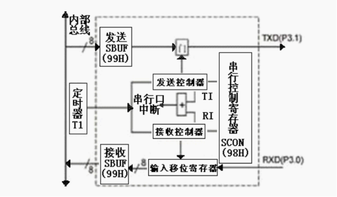
Send command: MOV, SBUF, A Receiving instruction: MOV A, SBUF
1. Serial port control register SCON (address: 98H)
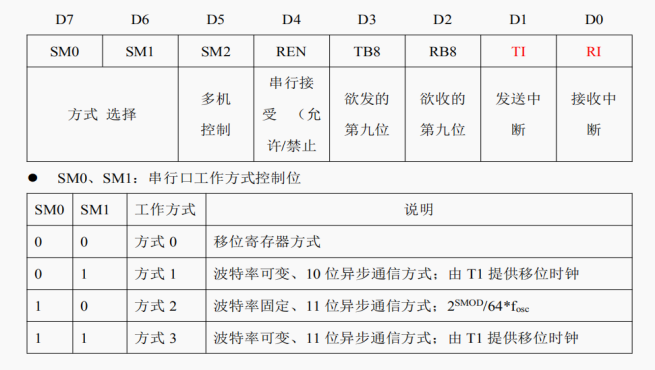
- TI: send interrupt flag bit. It must be cleared by software before sending.
- RI: receive interrupt flag bit. It must be cleared by software before receiving.
- SM2: multi machine communication control bit.
2. Power control register PCON (address: 87H)

3. Whether sending / receiving a frame of data ends or not?
(1) Query method: Sender: send one data ----- query TI ------ send the next data (send first and then query) Receiver: query RI ----------- read in a data ----------- query RI ----- (check first and then receive)
(2) Interrupt mode: Sending and receiving share a serial port interrupt 0023H. After the interrupt response, the service program should judge which interrupt it is. For example: JB, Ti, LOOP; Ti = 1, jump to LOOP sending program
Sender: Send a data ---- wait for the interrupt and send the next data in the interrupt service program Receiver: wait for an interrupt and receive data in the interrupt service program Note: the software must clear TI or RI after sending or receiving data, whether it is query or interrupt Note: CLR TI; CLR T1
3, Experimental content
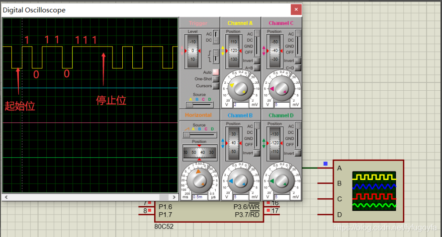
1. Send the same data repeatedly and observe the waveform output by TXD terminal.
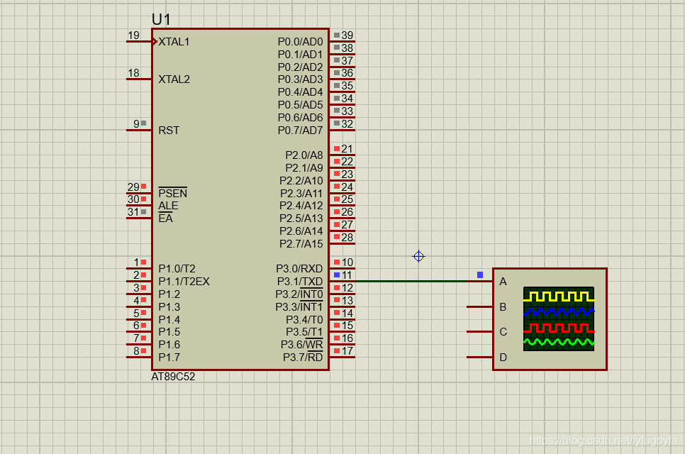
P3.1 multiplex it into serial transmitter TXD, connect it to oscilloscope and observe the output waveform. Observe the start and stop bits before and after the 8-bit data bit.
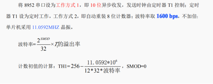
Example: set the serial port to working mode 1 and send data EDH=11101101B. Start sending from the low bit, 8-bit data, 1-bit start bit (low level), 1-bit stop bit (high level).
The simulation circuit is as follows:
The assembly language program is as follows:
      ORG   0000H
      JMP   MAIN
      ORG   0040H
MAIN:
      MOV   R0,#0EDH       ; Put the data 1 to be sent in R0
      MOV   TMOD,#20H      ; Timer T1 is used as baud rate generator timing operation mode 2
      MOV   TL1,#0EEH      ; Initial value of initialization timer
      MOV   TH1,#0EEH
      SETB  TR1           ;allow T1 timing
      MOV   SCON,#40H     ; Serial port working mode 1, send
      MOV   PCON,#0 The baud rate is not doubled
Loop:
      MOV   A,R0          ;Send the data to be sent to the accumulator
      MOV   SBUF,A        ;Write the data to be sent to the send buffer SBUF,Start serial port to send data
L1:
      JNB   TI,L1         ;Judge the interrupt flag bit after sending the application, and wait for the data to be sent circularly
      CLR   TI            ;The software clears the transmission interrupt flag bit to ensure that the next frame of data can be transmitted
      MOV   TH1,#0EEH     ; Reset timer initial value
      MOV   TL1,#0EEH
      SJMP  Loop          ;Send the same data circularly

      END
The simulation results are as follows:
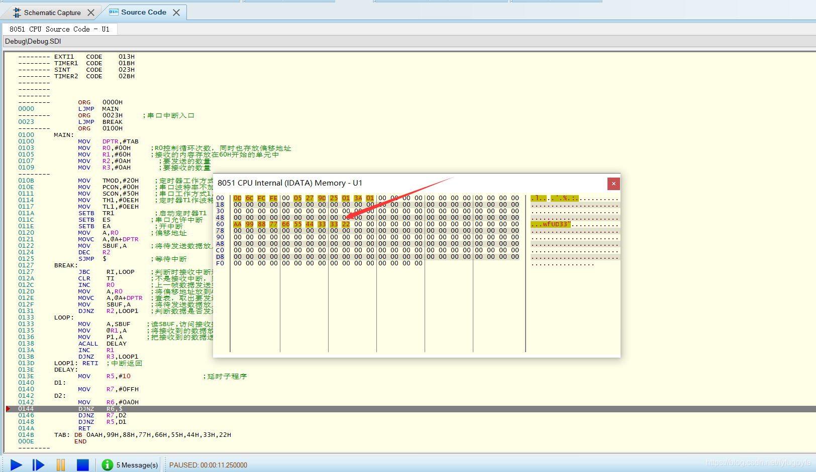
2. Spontaneous self collection. Send and receive the 10 data defined in the code segment through the serial port, send the received data to P1 port for display with LED light, and send it to the unit starting from the internal data storage space 60H. Requirements: data transmission and reception shall be interrupted.
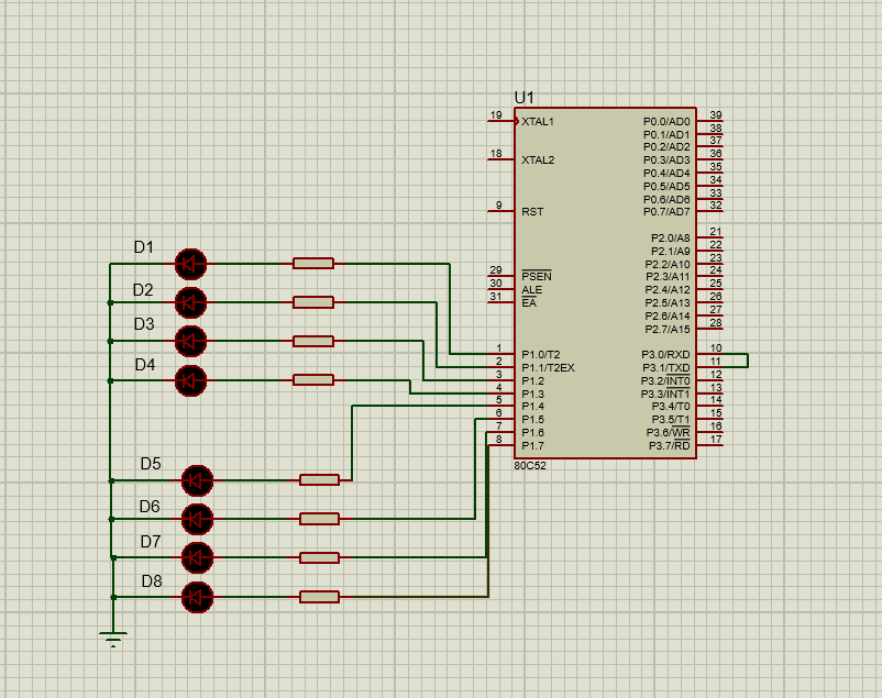
The simulation circuit is as follows:
Tips are as follows:
- 1. P3.0 receiver P3.1 sender
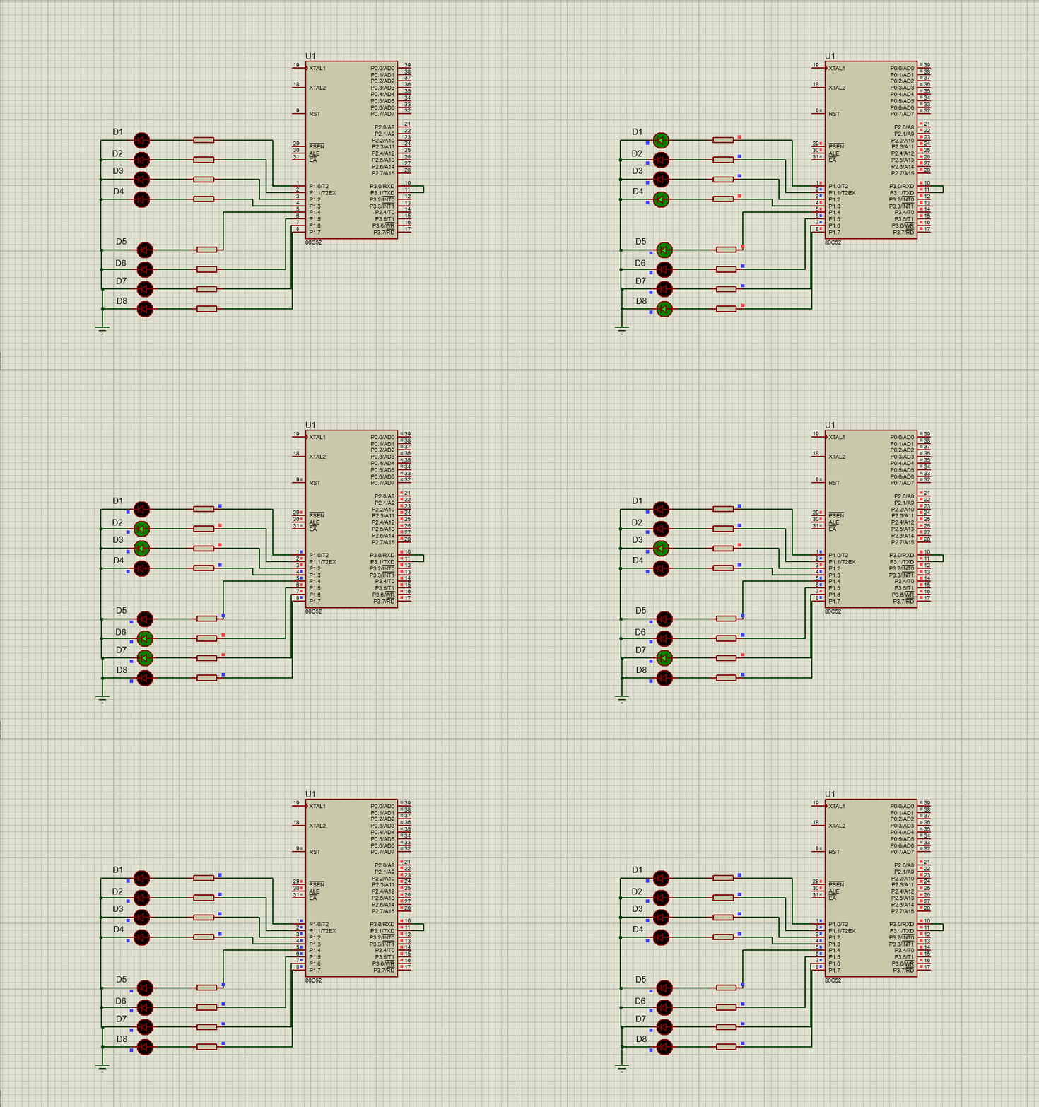
- 2. Each data is sent to the LED light for display, and a delay program shall be added
- 3. Enter the interrupt service program to determine whether to send or receive an interrupt
The assembly language program is as follows:
      ORG   0000H
      LJMP  MAIN
      ORG   0023H     ;Serial port interrupt entry
      LJMP  BREAK
      ORG   0100H
MAIN:
      MOV   DPTR,#TAB
      MOV   R0,#00H     ;R0 controls the number of cycles and also stores the offset address
      MOV   R1,#60H     ; The received content is stored in the unit starting from 60H
      MOV   R2,#0AH       ; Number of to send
      MOV   R3,#0AH       ; Quantity to receive

      MOV   TMOD,#20H    ; Timer working mode 2
      MOV   PCON,#00H    ; Serial baud rate is not doubled
      MOV   SCON,#50H    ; Serial port working mode 1, allowing reception; No check digit
      MOV   TH1,#0EEH    ; Timer T1 is used as baud rate generator. When fosc=11.0592Hz, RB=1600pbs
      MOV   TL1,#0EEH
      SETB  TR1          ;Start timer T1
      SETB  ES          ;Serial port interrupt allowed
      SETB  EA           ;Open interrupt
      MOV   A,R0        ;Offset address
      MOVC  A,@A+DPTR
      MOV   SBUF,A      ;Put the data to be sent into the send buffer
      DEC   R2
      SJMP  $           ;Wait for interrupt
BREAK:
      JBC    RI,LOOP    ;Judge whether to receive interrupt or send
      CLR    TI         ;If it is not a receive interrupt, it is a service interrupt caused by a send interrupt; Clear send interrupt flag
      INC    R0         ;After the data of the previous frame is sent, the offset address+1,Send next frame data
      MOV    A,R0       ;Place offset address in A in
      MOVC   A,@A+DPTR  ;Look up the table and take out the data to be sent
      MOV    SBUF,A     ;Put the data to be sent into the send buffer
      DJNZ   R2,LOOP1   ;Judge whether the data has been sent
LOOP:
      MOV    A,SBUF    ;read SBUF,Access receive data register
      MOV    @R1,A     ;Place the received data at 60 H In the starting unit
      MOV    P1,A      ;Send the received data to P1 Oral explicit
      ACALL  DELAY
      INC    R1
      DJNZ   R3,LOOP1
LOOP1: RETI  ;Interrupt return
DELAY:
      MOV    R5,#10                  ; Delay subroutine
D1:
      MOV    R7,#0FFH
D2:
      MOV    R6,#0A0H
      DJNZ   R6,$
      DJNZ   R7,D2
      DJNZ   R5,D1
      RET
TAB: DB 0AAH,99H,88H,77H,66H,55H,44H,33H,22H
     END
The simulation results are as follows:
The data stored in 60H unit is as follows:
Author: ye Tingyun CSDN: https://yetingyun.blog.csdn.net/