At the end of last semester, the subject is led lattice billboard, and the requirements at that time are as follows:
(1) LED dot matrix billboard with different characters;
(2) Press the key to switch between different display effects (such as flashing, static, pan, etc.);
(3) Press the key to switch between different display contents;
(4) Be able to display graphics or custom characters;
(5) Other functions (innovation part);
(6) System debugging, analysis, summary and function realization.
At that time, I used the STC89C51RD + single-chip computer of the general Chinese science and technology, but as long as it is a 51 single-chip computer, any 51 core chip can be replaced, as long as the circuit and program match.
The 51 single-chip microcomputer of the general Chinese technology that I used can determine the layout of the circuit directly by connecting wires, and does not need to re weld a circuit board by myself.
Then I connected the circuit according to the task requirements, wrote the corresponding program, and proteus simulation
1, Design ideas
First, P1 connects 8 independent keys, P3.4,P3.5,P3.5 three I/O ports control led lattice through analog SPI (51 single chip microcomputer has no hardware SPI bus controller).
The following is the program content of three I/O ports including header file, definition of independent keyboard and Simulation of SPI, including redefining function variables, which can effectively reduce the burden of programming.
#include <reg51.h>
#include <intrins.h>

#define  GPIO_KEY P1  //P1 port for independent keyboard

//--Redefining function variables--//
#define uchar unsigned char
#define uint  unsigned int
#define ulong unsigned long

//--Define IO to be used by SPI--//
sbit MOSIO = P3^4;
sbit R_CLK = P3^5;
sbit S_CLK = P3^6;
After that, the text and symbol displayed on led dot matrix are designed. (at that time, I designed the names of my team members and some custom symbols.).
The effect to be achieved is: press K1 after turning on the power, a pile of Chinese characters will move from top to bottom, press K2, the Chinese characters will flicker (flicker display is to display one word for a few seconds, and then display other words successively), press K3, which is the flicker display of those characters customized by me, and then press K8 to exit this function after entering each function, and then press K1, K2 Or K3 to access these three functions.
Two. Simulate SPI sending data through I/O port
(1) The simulation of transmission data function and corresponding module
The following is the function of sending data by simulating SPI through I/O port provided by the MCU of Puzhong science and technology. Because there is a matching font generation software, I will not write too much about this part. Those who want the font software can download it on Baidu online disk link at the end of the article.
//Send four bytes of data via 74HC595
void HC595SendData(uchar BT3, uchar BT2,uchar BT1,uchar BT0)
{
	uchar i;

	//--Send first byte--//
	for(i=0;i<8;i++)
	{
		MOSIO = BT3 >> 7 ;	//From high to low
		BT3 <<= 1;

		S_CLK = 0;
		S_CLK = 1;
	}

	//--Send first byte--//
	for(i=0;i<8;i++)
	{
		MOSIO = BT2 >>7;		//From high to low
		BT2 <<= 1;

		S_CLK = 0;
		S_CLK = 1;
	}

	//--Send first byte--//
	for(i=0;i<8;i++)
	{
		MOSIO = BT1 >> 7;		//From high to low
		BT1 <<= 1;
		S_CLK = 0;
		S_CLK = 1;
	}

	//--Send first byte--//
	for(i=0;i<8;i++)
	{
		MOSIO = BT0 >> 7;		//From high to low
		BT0 <<= 1;
		S_CLK = 0;
		S_CLK = 1;
	}

	//-- output / /
	R_CLK = 0; //set dataline low
	R_CLK = 1; //Chip selection
	R_CLK = 0; //set dataline low
}
In this part, four 74HC595 are used. The following is the corresponding simulation picture. RX8 in it is the exclusion. No, I have this picture because there is this exclusion in the schematic diagram given by Puzhong technology. When I do the simulation, I directly draw a tiger and a cat. In fact, it's not necessary at all. The reason why there is this on the board of Puzhong is to separate each module and use the arrangement line when connecting Just connect, POS and NEG can be understood as rows and columns of 1616 LED lattice.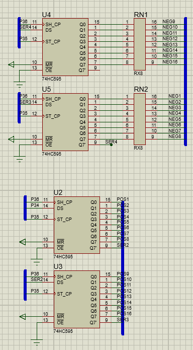
The requirement of LED lattice is 1616, which needs to be combined with four 88 LED lattice. The manufacturing method in proteus is as follows: Here
, I spliced 1616 LED lattice according to this, and then wrote the network label of the pin according to the schematic diagram given by Pu Zhong, and marked it in proteus (Note: the network label of this diagram is wrong), and then the result of simulation is wrong. I redrawn it many times, which may be the problem of the schematic diagram, or other reasons, using the board of Pu Zhong technology My friends can note that it's not right for me to draw a picture simulation according to this principle. At last, 16 lines are labeled with POS1 to POS16 respectively, and 16 columns are labeled with NEG1 to NEG16.
The following is the lattice simulation diagram that can be used finally: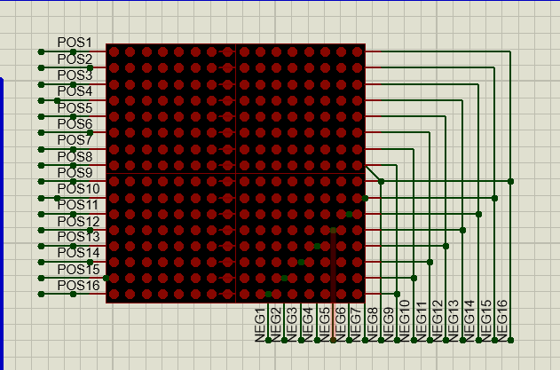
The following is the schematic diagram (there is a problem with the network label according to the drawing, and there is no problem with the others):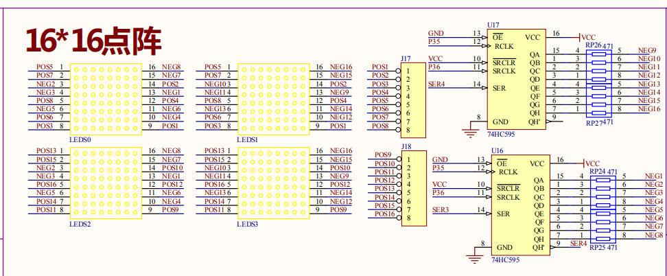
The following is the simulation of the drawing according to the principle (it can't be used after drawing twice, and the pattern is inconsistent with the expectation):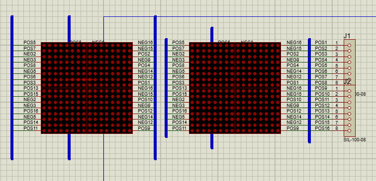
(2) Data to transfer
The transmitted data needs to select some Chinese characters, characters or custom symbols.
Here are the arrays corresponding to some last names and custom characters. tab0 is used to determine the display position, which will be mentioned below.
//Lattice display array
uchar code tab0[] = {0x00, 0x01, 0x00, 0x02, 0x00, 0x04, 0x00, 0x08,
					 0x00, 0x10, 0x00, 0x20, 0x00, 0x40, 0x00, 0x80,
					 0x01, 0x00, 0x02, 0x00, 0x04, 0x00, 0x08, 0x00,
					 0x10, 0x00, 0x20, 0x00, 0x40, 0x00, 0x80, 0x00};
//-- Zhang / /
uchar code tab1[] = {
128,1,191,49,176,49,176,25,176,13,190,7,134,
1,230,255,134,7,190,13,176,13,176,25,176,49,176,103,158,195,140,1};
//-- Wang / /
uchar code tab1[] = {
0,0,252,31,128,0,128,0,128,0,128,0,128,0,248,
15,128,0,128,0,128,0,128,0,128,0,254,63,0,0,0,0};
//-- Li / /
uchar code tab2[] = {
128,0,128,0,254,63,160,2,144,4,136,8,6,48,240,
3,0,1,128,0,254,63,128,0,128,0,224,0,0,0,0,0};
//- Ren - / /
uchar code tab3[] = {
16,0,16,28,208,3,8,2,8,2,12,2,10,2,232,63,8,2,
8,2,8,2,8,2,8,2,200,31,0,0,0,0};
//-- Xu / /
uchar code tab4[] = {
16,2,16,2,8,5,132,8,82,16,176,47,8,2,12,2,202,
31,8,2,72,18,72,34,40,34,136,3,0,0,0,0};
//-- Yang / /
uchar code tab5[] = {
24,0,152,63,24,24,24,12,127,6,24,3,156,255,60,
219,126,219,126,219,155,217,152,205,216,204,120,198,24,123,152,49};
//- peach heart - / /
uchar code xin[] = {
0,0,28,56,252,63,254,127,255,255,207,243,135,
225,7,224,15,240,30,120,60,60,120,30,240,15,224,7,192,3,128,1};
//--Pentagram--//
uchar code char1[] = {
128,1,128,1,192,3,192,3,192,3,96,6,127,254,6,
96,28,56,48,12,48,12,152,27,248,30,56,28,12,48,0,0};
//-- circle / /
uchar code char2[] = {
0,0,224,7,120,30,28,56,28,56,14,112,14,112,14,
112,14,112,14,112,28,56,28,56,120,30,224,7,0,0,0,0};
//- trigonometry - / /
uchar code char3[] = {
0,0,128,1,128,1,192,3,192,3,96,6,96,6,48,12,48,
12,24,24,24,24,12,48,12,48,254,127,0,0,0,0};
//- diamond shaped - / /
uchar code char4[] = {
128,0,64,1,32,2,16,4,8,8,4,16,2,32,1,64,2,32,
4,16,8,8,16,4,32,2,64,1,128,0,0,0};
//- arrow - / /
uchar code char5[] = {
0,0,0,0,0,0,0,2,0,4,0,8,0,16,0,32,126,64,0,
32,0,16,0,8,0,4,0,2,0,0,0,0};
After that, the array to be displayed will be mixed into a new pointer array. This array is used directly in the function of lattice display. Many of the pointer arrays of * p are names deleted by me, leaving only the last name.
uchar *p[] = {tab1, tab2, tab3, tab4, tab5, tab6, tab7, tab8,
							tab9, tab10, tab11, tab12, tab13,	tab14};
uchar *c[] = {char1, char2, char3, char4,char5};
3, Detect independent keys
First of all, the main function is while(1), infinite loop. As long as no key value is detected (i.e. any key in the independent key is pressed), the main function will be looped all the time, and the screen clearing program (i.e. calling the transfer data function in Title 2, respectively transferring 0xff, 0xff, 0, 0) will be executed. If the key value is detected, it will enter the corresponding function and enter the corresponding function of each function.
Here is the main function:
void main(void)
{
   while(1)
   {
		 HC595SendData(0xff,0xff,0,0);	//Clean screen
		 keyNum=Key_Scan();		//Read Key
		 switch (keyNum)
		{
			case(0xFE) :	  //Return the data of key K1
				translation();//Text pan up to down
				break;
			case(0xFD) :	  //Return the data of key K2
				twinkle1();		//Text flicker
				break;
			case(0xFB) :	  //Return the data of key K3
				twinkle2();		//Symbol flicker
				break;
//			case(0xF7): / / returns the data of key K4
//				;
//				break;
//			case(0xEF): / / returns the data of key K5
//				;
//				break;
//			case(0xDF): / / returns the data of key K6
//				;
//				break;
//			case(0xBF): / / returns the data of key K7
//				;
//				break;
			case(0x7F) :	  //Return the data of key K8
				HC595SendData(0xff,0xff,0,0);				//Clean screen
				break;
			default:
				break;
		}
   }
}
Read Key
As mentioned earlier, P1 is defined as an independent key, i.e. GPIO key in the program. When the independent key is pressed, GPIO key! = 0xff, then eliminate jitter (i.e. delay 10 ms) and detect again. If the key is detected as pressed, save the key value in the keyValue, and then release the key or do not release the key after 500 ms, the read key value will be returned.
unsigned char Key_Scan()
{
	unsigned char keyValue = 0 , i; //Save key values

	//--Test key 1--//
	if (GPIO_KEY != 0xFF)		//Check whether key K1 is pressed
	{
		Delay10ms(1);	//Eliminating jitter

		if (GPIO_KEY != 0xFF)	//Check whether the key is pressed again
		{
			keyValue = GPIO_KEY;
			i = 0;
			while ((i<50) && (GPIO_KEY != 0xFF))	 //Check whether the key is released
			{
				Delay10ms(1);
				i++;
			}
		}
	}

	return keyValue;   //Returns the value read to the key value
}
4, Specific functions
(1) Text moves from top to bottom
The key K 1 corresponds to the function of text moving from top to bottom. The following is the corresponding program, in which the embedded third cycle for (k = 0; K < 16; K + +) traverses from 0 to 15, corresponding to lines 1 to 16 of LED lattice, and the embedded second cycle for (MS = 10; MS > 0; MS –) determines the time of displaying the same content. The embedded first cycle is while(keyNum!=0x7F), as long as keyNum!=0x7F is one Once established, there will be infinite circulation.
i. How to press K8 at any time to exit the function and return to the main function
In the minimum cycle, a program to detect the key value is embedded, keynum = key ᦉ scan(); then judge whether it is 0x7F (that is, the key value when K8 is pressed). If it is, exit the cycle and return to the second cycle. In the second cycle, there is a program to determine whether the key value is K8. Similarly, if it is, return to the first cycle, while(keyNum!=0x7F) will also judge whether the key value is 0x7F, if not If yes, exit the loop and return to the main function.
ii. How to move text from top to bottom
When entering this function just before entering the cycle, assign j=0 (if j=0 is not assigned here, it is OK, but the next time entering this function, the image displayed at the end of this time will continue to shift downward). Send data to LED lattice in the third embedded cycle, that is, the smallest cycle, and send one line of data at a time, cycle 16 times, each time k+1 can display the whole The whole LED lattice, when k is added to 16, exits the minimum cycle. The second cycle for (MS = 10; MS > 0; MS –) determines the number of times to enter the minimum cycle, that is, the time to display. After the specified time is displayed, exit the second cycle, and return to the third cycle, j+1. Then, when entering the minimum cycle, the position in the pointer array corresponding to the first two bits of data sent will be added with 2j respectively, that is, the display The text or character of is moved up one bit, and the line that is left blank at the bottom will be replaced by the first line of the next text or character. Similarly, the effect of text moving up is formed. A word needs 16 lines, starting from 0. When j=15 the number of text or characters to be displayed, make j=0, and display from the first word again.
Here is the procedure for text movement:
//Text translation from top to bottom
void translation()
{
	j=0;
	while(keyNum!=0x7F)
	{
		for(ms = 10; ms > 0; ms--)	//Mobile freeze frame time setting
		{
			for(k = 0; k < 16; k++)	//Show a word
			{
				HC595SendData(~(*(p[0] + 2*(k+j) + 1)),~(*(p[0] + 2*(k+j) )),
				tab0[2*k],tab0[2*k + 1]);
				//Because the array selected by the font software is high level valid, the column should be inverted
				keyNum=Key_Scan();
					if(keyNum==0x7F)
						break;
			}
			HC595SendData(0xff,0xff,0,0);										   //Clean screen
			if(keyNum==0x7F)
				break;
		}
		j++;
		if(j == (14*15) )
		{
			j = 0;
		}
	}

}
The following is the effect of text movement (at this time, the first word has disappeared by nearly half, and the next word also shows a small half, namely "Wang" and "Li"):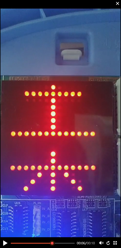
(2) Text flashing
i. How to press K8 at any time to exit the function and return to the main function
It is the same as the function of text moving from top to bottom, except that the text blinking function has four cycles, one more than text moving. It also detects the key value in the minimum cycle. If keyNum==0x7F is detected, it exits step by step, and finally returns to the main function.
ii. How to realize text flashing display
Similar to text movement, data is sent from the first line of LED dot matrix to the last line in the minimum cycle. The last cycle determines the total number of times the minimum cycle runs, that is, the time to display a word. In the last cycle, each time i+1 decides to display the next word. When i=14, it goes back to the outermost cycle, and then it goes back to the previous cycle and starts again from the first text Start showing.
In the second cycle, I will cycle as many times as there are text to be displayed. For example, if I originally designed 14 texts, I < 14 in for (I = 0; I < 14; I + +).
Here is the procedure for flashing text:
//Text flicker
void twinkle1()
{
	while(keyNum!=0x7F)
	{
		for(i = 0; i < 14; i++)		//14 words in total
		{
			for(ms = 50; ms > 0; ms--)	//Display 50 times, i.e. visual recognizable residence time
			{
				for(k = 0; k < 16; k++)			//Show a word
				{
					//--Because the array selected by the font software is high level valid, the column should be inverted--//
					HC595SendData(~(*(p[i] + 2*k + 1)),~(*(p[i] + 2*k )),
												 tab0[2*k],tab0[2*k + 1]);
					keyNum=Key_Scan();
					if(keyNum==0x7F)
						break;
				}
				HC595SendData(0xff,0xff,0,0);				//Clean screen
				if(keyNum==0x7F)
					break;
			}
			if(keyNum==0x7F)
						break;
		}
	}
}
The following is the effect of text flickering. Only one text is displayed in a moment: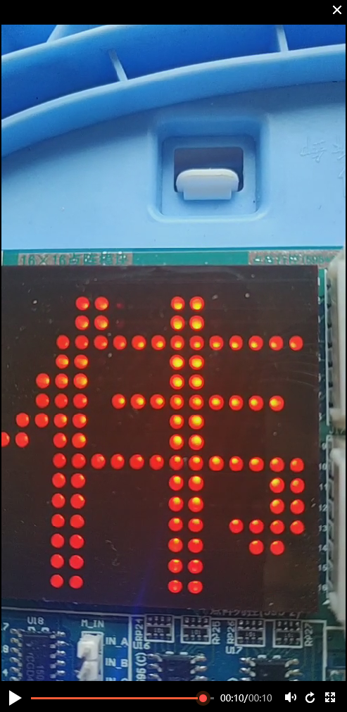
(3) Symbol flashing display
Its principle is exactly the same as text flashing display, except that the pointer array contained in this program is full of custom symbols.
Here is the procedure for flashing symbols:
//Symbol flicker
void twinkle2()
{
	while(keyNum!=0x7F)
	{
		for(i = 0; i <5; i++)		//5 words in total
		{
			for(ms = 50; ms > 0; ms--)	//Display 50 times, i.e. visual recognizable residence time
			{
				for(k = 0; k < 16; k++)			//Show a word
				{
					//--Because the array selected by the font software is high level valid, the column should be inverted--//
					HC595SendData(~(*(c[i] + 2*k + 1)),~(*(c[i] + 2*k )),
												 tab0[2*k],tab0[2*k + 1]);
					keyNum=Key_Scan();
					if(keyNum==0x7F)
						break;
				}
				HC595SendData(0xff,0xff,0,0);				//Clean screen
				if(keyNum==0x7F)
						break;
			}
			if(keyNum==0x7F)
						break;
		}
	}
}
The following is the effect of symbol blinking. Only one custom symbol is displayed in a flash: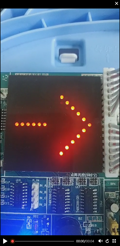
(4) Innovation part
When we do this program, we are about to take the final exam, so we don't bother to do the innovation part, but it's actually very simple. For example, we can make the symbols move from top to bottom, flash for a while and move for a while, for example, we can set the things to be displayed horizontally, then flash to display a person's name, and then move to display I LOVE YOU. Even if there is a passive buzzer You can also play a song while it is displayed.
5, proteus simulation
The following is the simulation I made with proteus, the simulation effect will not let go, that is, the LED dot matrix displays the same thing in the single chip computer before.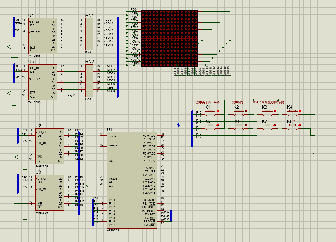
PS: Font software network disk link:
Link: https://pan.baidu.com/s/1xrshrlye3dnwllnddi8txq
Extraction code: j9u8

