Question note:
When we use 51 MCU, we will find that there is only one RX and TX, but in order to achieve a complete data acquisition, upload and management, a serial port is not enough (acquisition devices generally need a pair of serial ports, and communication devices also need a pair of serial ports). Then the problem arises. 51 MCU only provides a serial port. What should we do?
-
The analog TTL serial port in this paper is realized by using IO port of 51 single chip computer. We know that all IO ports of MCU can control its high and low level (1/0), and we need to use it to simulate TTL serial port, we first know the working principle of TTL serial port.
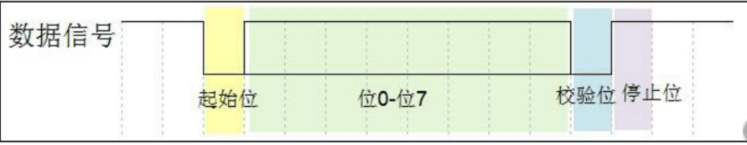 This is shown in the figure above.
Starting bits: represented by data bits of a logic 0End bit: represented by data bits of 0.5, 1, 1.5 or 2 logical 1
Valid data: Valid data is immediately followed by valid data. The length of valid data is usually agreed to be 5, 6, 7 or 89 bits.
Check bits: optional, for data anti-jamming (I have not used it) is quoted
Specific to see Introduction of Serial Port Protocol -
The baud rate of serial communication, in the final analysis, is only the duration of each level. The higher the baud rate, the shorter the duration. If the baud rate is 9600 bps, the transmission time of each bit is 1000 ms/9600 = 0.104 ms, and the delay between bits is 0.104 Ms.
-
Single-chip microprocessors often use 11.0592M crystal oscillator. Sensors usually use 11.0592M wave rate to communicate. With this frequency, the time of each instruction cycle (the time to take out the instruction and execute it) is (12/11.0592)us, and the instruction cycle s=(1000000/9600)/(12/11.0592)=96 with a baud rate of 9600, which is just an integer. So it is convenient for us to use program instructions to achieve more accurate delay.
-
Now let's get to the point! Generally, there are three methods to simulate serial port. We take 11.0592M crystal oscillator 9600 baud rate as an example. The following methods are available through my own tests.
Method 1: Delay method
This method uses the method of instruction period delay to simulate baud rate to realize serial communication. It is relatively simple and widely used. It is also suitable for analog multi-serial communication. However, it requires high accuracy of sampling. It needs to repeatedly debug the delay of instruction period. I have passed 51 experiments and sometimes the data transmitted will be wrong. Unstable, so not recommended.
As you know from the above calculation, each bit of serial port needs to be delayed by 0.104 seconds, and 96 instruction cycles can be executed in the middle.
#include "reg52.h"
#define uchar unsigned char
#define RXD P1_0//receiving foot
#define TXD P1_1// Send Foot
#define WRDYN 44//Write Delay
#define RDDYN 43//Read Delay
//Delay procedure*
void Delay2cp(unsigned char i)
{
while(--i); //i=1, two instruction cycles.
}
//Send a byte to the serial port
void WByte(uchar input)
{
uchar i=8;
TXD=(bit)0; //Send Start Bit
Delay2cp(39);
//Send 8-bit data bits
while(i--)
{
TXD=(bit)(input&0x01); //Previous Low Position
Delay2cp(36);
input=input>>1;
}
//Send check bits (none)
TXD=(bit)1; //Send End Bit
Delay2cp(46);
}
//Receive a byte from the serial port
uchar RByte(void)
{
uchar Output=0;
uchar i=8;
uchar temp=RDDYN;
//Receiving 8-bit data bits
Delay2cp(RDDYN*1.5); //Notice here that the starting bit is waited for.
while(i--)
{
Output >>=1;
if(RXD) Output |=0x80; //Receive low first
Delay2cp(35); //(96-26)/2, cycle occupies 26 instruction cycles
}
while(--temp) //Search for end bits within a specified time.
{
Delay2cp(1);
if(RXD)break; //Withdrawal upon receipt of the closing seat
}
return Output;
}
Method 2: Counting
This method generates accurate baud rate by counting the clock of single chip computer to realize serial port simulation. This method is more accurate, so long as the baud rate is correct, communication can be realized. (Only the sending part)
void S2INI(void)
{
TMOD |=0x02; //Counter 0, mode 2
TH0=0xA0; //Predicted values are 256-96 = 140, hexadecimal A0
TL0=TH0;
TR0=1; //Start counting
TF0=0;
}//Counter initialization


void WaitTF0( void )
{
while(!TF0);
TF0=0;
}//Query counter overflow flag bit

//Send a byte of data to the serial port, the procedure is the same as above.
void WByte(uchar input)
{
uchar i=8;
TR0=1;
TXD=(bit)0;
WaitTF0();
while(i--)
{
TXD=(bit)(input&0x01);
WaitTF0();
input=input>>1;
}
TXD=(bit)1;
WaitTF0();
TR0=0;
}
Method 3: Interruption method
Similar to the counting method, it is not explained. (Only receive)
#define TM0_FLAG P1_2// Set Transport Flag Bit
//Counter and interrupt initialization
void S2INI(void)
{
TMOD |=0x02; //Counter 0, mode 2
TH0=0xA0; //Predicted values are 256-96 = 140, hexadecimal A0
TL0=TH0;
TR0=0; //Use only after sending or receiving
TF0=0;
ET0=1; //Allow timer 0 interrupt
EA=1; //Interruption allowable main switch
}
//Receive a character
uchar RByte()
{
uchar Output=0;
uchar i=8;
TR0=1; //Start Timer0
TL0=TH0;
WaitTF0(); //Equivalent starting position
//Receiving 8-bit data bits
while(i--)
{
Output >>=1;
if(RXD) Output |=0x80; //Receive low first
WaitTF0(); //Inter-bit delay
}
while(!TM0_FLAG) if(RXD) break;
TR0=0; //Stop Timer0
return Output;
}
//Interrupt 1 Processor
void IntTimer0() interrupt 1
{
TM0_FLAG=1; //Set the flag bit.
}
//Query Transport Flag Bit
void WaitTF0( void )
{
while(!TM0_FLAG) ;
TM0_FLAG=0; //Clear Sign Location
}
Statement: This code is intercepted online, not my own code, but the method is really available. I only share the methods and learning process here. If I can't achieve it, I can communicate with myself and learn from each other.